Advanced Mapping Systems To Guide Atrial Fibrillation Ablation: Electrical Information That Matters
Sotirios Nedios, MD, Philipp Sommer, MD, Andreas Bollmann, MD, PhD, Gerhard Hindricks, MD
Department of Electrophysiology, Heart Center, University of Leipzig, Germany.
Catheter ablation is an established and widespread treatment for atrial fibrillation (AF). Contemporary electroanatomical mapping systems (EAMs) have been developed to facilitate mapping processes but remain limited by spatiotemporal and processing restrictions. Advanced mapping systems emerged from the need to better understand and ablate complex AF substrate, by improving the acquisition and illustration of electrophysiological information. In this review, we present you the recently advanced mapping systems for AF ablation in comparison to the established contemporary EAMs.
Key Words : Electroanatomic Mapping, Atrial Fibrillation, High Density Mapping.
Correspondence to: Sotirios Nedios, Department of ElectrophysiologyHeart Center, University of Leipzig Strümpellstr. 3904289 Leipzig, Germany.
Atrial fibrillation (AF) is the most common arrhythmia with an increasing prevalence and a high socio-economical health burden. Catheter ablation (CA) is an established and widespread AF treatment. After the initial discovery and abolishment of focal pulmonary vein (PV) activity as AF triggers,1-3 CA treatment has undergone considerable improvement over the last years aiming always for better results with faster, safer and easier procedures.
Electrical pulmonary vein isolation (PVI) is the cornerstone of AF treatment.4-6 In patients with paroxysmal AF, recovered PV conduction is the most common reason for recurrence and can be successfully treated by a new ablation session.7,8 In patients with chronic AF though, success-rates are lower and AF triggers from a diseased left atrium (LA) are more common, requiring additional substrate modification, defragmentation or linear ablations.9,10 Multiple atrial wavelets, macro-reentries, and localized sources (drivers) have been reported to contribute to this substrate.11,12
Achieving electrically continuous, transmural lesions in a beating heart is challenging and requires a reliable three-dimensional (3D) navigation, in order to avoid complications (PV stenosis, perforation, phrenic nerve or esophageal injury). In order to facilitate this task with less radiation than plain fluoroscopy, electroanatomical-mapping systems (EAMs) have been developed, enabling the tracking of intracardiac electrodes in 3D maps and the navigation of catheter ablation.
Conventional mapping systems though cannot adequately detect localized AF drivers due to their sequential spatiotemporal characteristics, their intermittent firing and spatial meandering.13 For this reason advanced mapping tools have been developed to visualize and better understand the AF-maintaining drivers. These systems have shown promising results for AF ablation and could path the way to a new era of substrate characterization and individual ablation strategies. In this context, the current article aims to review the modern advanced mapping systems for AF ablation in comparison to the established contemporary EAMs.
Contemporary Mapping Systems
All mapping systems are based on non-fluoroscopic visualization of mapping catheters and a 3D reconstruction created by the manipulation of a mapping catheter. Electrical information at map points is recorded and can be used for the color-coded display of the electrical activation sequence known as “activation mapping”, the display of post-pacing intervals known as “entrainment mapping” or the display of unipolar/bipolar electrograms as part of “fractionation” or “voltage mapping”.14 The most common EAMs for AF ablation are the Carto (Biosense Webster, Baldwin Park, CA, USA) and the EnsiteNavX system (St. Jude Medical, St. Paul, MN, USA).
The latest version of Carto system is based on a hybrid of magnetic and current-based catheter localization technology and enables visualization of multiple catheters simultaneously. Three active magnetic fields generated by a location pad placed underneath the patient act on mini-sensors embedded in the catheter tip providing information about its exact position and orientation, in relation to a reference sensor on the skin. Additionally, six electrode patches positioned at the patient’s back and chest, screen a unique current
emitted from different catheter electrodes.15 Multipolar mapping
catheters can be used for fast anatomical mapping (FAM) by
registering and reentering 3D models. Respiratory gating is possible
through thoracic impedance measurement, but patient movement or
dislocation of the location pad may lead to uncorrectable map shifts.
In order to enhance recognition of anatomical variations, integration
of pre-aquired CT/MRI data or intraprocedural inctracardiac
echocardiography (ICE, CartoSound®, Biosense Webster) is possible
through merging of the 3D models.16
The EnsiteNavX Velocity system is based on an impedance-based
tracking technology, capable of tracking intracardiac electrodes as
well as tagging points in a high-frequency (8 kHz) electric field
produced by six skin electrodes. The 3D-localization of the catheters
is calculated based on an impedance gradient in relation to a reference
electrode.17 A process called field-scaling aims to correct for the body’s
non-linear impedance and the use of intracardiac refrence-catheters
reduces motion artifacts. However, dislocation of the reference
catheter may lead to uncorrectable map shifts. EnsiteNavX allows
for visualization of multiple catheters from different manufacturers
and simultaneous collection of anatomical and electrophysiological
data from all electrodes of any catheter.18 Integration of CT/MRI
data though requires an extensive registration called fusion.19
Both of these EAMs have been proven to reduce radiation and
procedural duration20-22 and in combination with pre-acquired imaging
data can lead to less complications and better results.23,24
Additionally,
integration of electrode-tissue contact force data by special catheters
(SmartTouch, Biosense Webster or TactiCath, St. Jude Medical) can
provide feedback for lesion creation and improve efficacy, reduce risks
and procedural parameters.25-29 The most important contribution of
these systems though is the characterization of the AF substrate
through fractionation (quality and temporal characteristics of the
electrical signals) or voltage mapping (amplitude of electrical signals),
which has been the stimulus for further mapping developments.
These tools aim to identify additional ablation targets and allow a
patient-tailored approach.
Complex fractionated atrial electrograms (CFAEs) are regarded as
surrogates of asynchronous activation of myocyte bundles through
a fibrotic myocardium. They are defined as atrial electrograms with
low voltage (≤0.15 mV) signals with ≥2 deflections/perturbations
of the baseline with continuous deflection of a prolonged activation
complex; and/or a very short cycle length (≤120 milliseconds), with
or without multiple potentials. The mechanisms of CFAEs creation
has been related to factors which perpetuate AF, but it has been also been
considered to be passive consequences of near-by rapid AF drivers.30
Contemporary EAMS integrate automated algorithms that provide
CFAEs maps, but this has not been proved superior to conventional
CFAE mapping and ablation.31 Despite the initally encouraging results,
recent studies showed a higher rate of resulting atrial tachycardias
and failed to reveal a benefit of additional CFAE ablation.32,33
Voltage mapping is based on the correlation of low-voltage
areas (<0.5 mV) in the left atrium with endocardial scar and/
or structural defects as a substrate that can diminish success rates
after AF ablation.
34-38
Supplementary ablation of low-voltage zones
as an additional target to PVI serves as an individualized substrate
modification (similar to unstable ventricular tachycardias). According
to our experience such low-voltage areas are found in 35% of patients
with persistent AF and in 10% of patients with paroxysmal AF, most
commonly in the septal, anterior, or posterior LA wall. Patients with
low-voltage substrate have lower success rates after AF ablation (23%
after PVI only) that can be significantly improved by targeting these in
a patient-tailored approach (70% after a year). Moreover, this strategy
could spare the majority of patients (2/3 of those with persistent AF)
from additional ablation lesions and potential complications, without
compromising the ablation outcomes.39 Prospective, randomized
clinical studies are needed to clarify the role of a voltage-based AF
ablation in comparison to established strategies.
Contemporary EAMs have been very valuable for the navigation
of AF ablation, but have some limitations. The integrated automated
mapping algorithms are susceptible to annotation and interpolation
errors that require a manual point-by-point verification of annotated
points. This is a time-consuming process that is prone to incorrect
judgment regarding signal selection, the window-of-interest and
the presence of fragmented/double potentials or areas of verylow
continuous potentials. Moreover, spatiotemporal analysis and
registration of electrograms on a map as well as the creation of a
new map in case of tachycardia change, remains a slow process
limited by the speed of signal acquisition. The need to overcome
these disadvantages and to improve illustration of the underlying
AF mechanisms, has led to the development of advanced mapping
systems.
Advanced mapping systems for AF ablation have focused on
improving signal quality (high-resolution), acquisition and processing
time, precision of annotation and development of automated
algorithms that visualize electrophysiologic information. These
efforts refer once again to the core principle of electrophysiology: the
electrical signals, which guide AF ablation, should be reliable (with
high resolution and low noise), appropriately acquired and processed
in a timely manner. In this sense, new diagnostic catheters and novel
mapping technics have been developed and will be presented here.
Ripple Mapping is a novel technique that displays time-voltage
data as dynamic bars on Carto surface shells.40 Electrograms are
visualized as color bars on 3D models, changing colors and dimensions
according to the voltage-time relationship, time-gated to a preselected
electrograms (reference). The operator has the impression
of a “wave-like” movement of the propagation, without any manual
or automatic annotations. This way ripple mapping compensates for
isolated annotation and interpolation errors and as recently reported,
demonstrates higher diagnostic accuracy for atrial tachycardias
compared to conventional activation mapping.41 Although it is an
offline system that requires time for post-processing, ripple mapping
has the potential to simplify mapping and minimize operatordependence.
Further evaluation and comparison with other systems
is needed to prove if this technology will be integrated in “real-time”
clinical practice.
High Dominant Frequencies Mapping
Dominant frequency (DF) maps derive by high-resolution analysis
of the Fourier power spectrum and enable the color-coded hierarchical
visualization of frequencies in combination with contemporary
catheters and EAMs.42 High DF sites are defined by 20% frequency
gradient relative to the surrounding tissue and represent localized
reentrant sources (ablation-targets). Multiple DF sites are usually
found in a patient with variable distribution (predominantly PVsites
in paroxysmal and more atrial sites for persistent AF) and intraprocedural
spatiotemporal stability, which has raised some concern
about their role as AF drivers. Ablation of DF sites may result in
significant slowing of AF cycle length, reduction of AF inducibility,
and AF termination especially in paroxysmal AF patients.43,44 The
RADAR-AF study compared DF ablation vs. circumferential
PVI and found no incremental value for persistent AF but a noninferiority
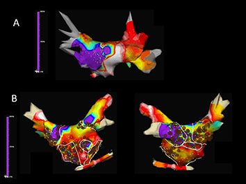
for paroxysmal AF (Fig. 1).45 However, more clinical
studies are needed to further evaluate the role of DF ablation.
Figure 1 Time-frequency analysis of atrial fibrillation (AF) with Dominant Frequency (DF) maps showing A. a patient with paroxysmal AF in whom DF guidead isolation of the left inferior pulmonary vein antrum lead to AF termination and B. a patient with persistent AF in whom a combined ablation approach with both high-frequency source ablation and circumferential pulmonary vein isolation was performed (Courtesy of Felipe Atienza, Hospital General Universitario Gregorio Marañón, Madrid, ES)
Focal Impulse and Rotor Mapping
In order to improve the identification and abolishment of local
reentrant sources a novel computational approach with the concept
of focal impulse and rotor modulation (FIRM) has been developed.46
For this technique, a dedicated 64-pole basket catheter (8 splines
with 8 electrodes per spline) is used for panoramic intra-cardiac
mapping during AF. Automated intra-procedural processing by the
RhythmView mapping system (Topera, Menlo Park, CA, USA)
enables the depiction of AF propagation maps projected onto grids.
These maps are then used to guide ablation of AF drivers (usually 2-3
rotors or focal impulses per patient). Rotors are defined as stable and
sustained spiral activation around a center of rotation, whereas focal
impulses are defined by centrifugal activation from a source. Target
sites are located by their electrode coordinates and radiofrequency
ablation with a conventional catheter is usually applied for 15–30 sec
up to 10 min, aiming for slowing or termination of AF. Conventional
EAMs can integrate tracking of the basket catheter, annotation of
target and ablation sites and simultaneous creation of atrial geometries,
which may then be used for PV isolation (Fig. 2).
Figure 2 Electroanatomical map (Carto 3, UniVu®) with annotation of AF rotors located by the RhythmView mapping system (Topera) on the right (grey shell, red points; I) and the left atrium (fused with a green 3D CT shell): close to the left atrial appendage (orange, II) and the mitral isthmus region (red, purple, blue, III). A circular mapping catheter (blue) is placed in the right superior pulmonary vein and an ablation catheter is at the posterior wall. The white points show the area of phrenic nerve capture

PVI with additional
direct or coincidental FIRM ablation has been shown to improve
mid-term and long-term AF ablation outcome.
46-48
Similar to other
technologies though, which are used to supplement conventional AF
ablation, additional costs and processing time remain an issue and
remain to be proofed for their clinical value.
Non-Invasive Body Surface Mapping
Body surface mapping (BSM) is a non-invasive bedside mapping
system that aims to identify AF drivers by using an array of multiple
surface electrodes and by projecting this information on a preacquired
CT/MRI-based 3D model of the atria. Initial research
revealed that using a 56-electrode vest around the patient’s torso,
non-invasive mapping could depict wavefront propagation maps
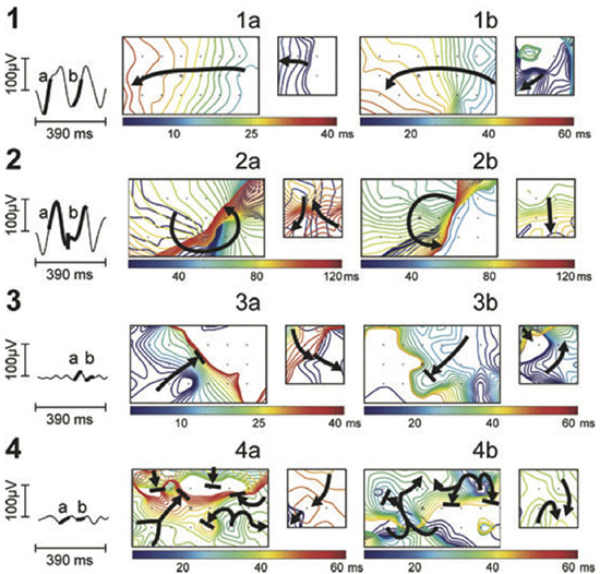
and identify specific patterns like single wavefronts, wave-breakages/
splitting or multiple simultaneous wavefronts (Fig. 3).49 Further
development of this kind of mapping led to a 252-electrode vest
connected to a special system (ECVUE, CardioInsight Technologies
Inc, Cleveland, OH) that records unipolar surface potentials. Biatrial
unipolar electrograms are then automatically reconstructed from
torso potentials and epicardial activation maps are computed by using the intrinsic deflection-based method. The windows with long
ventricular pauses (spontaneous or diltiazem-provoked) are usually
randomly selected for AF electrogram analysis. Maps of AF are
generated by algorithms with a combination of signal filtering and
phase mapping.50-53 Wave propagation is then depicted color-coded
on a beat-to-beat basis and spatiotemporal density maps are analyzed
to identify active driver regions (classified as focal or reentrant) and
the repetition of this activity. In contrast to focal impulse rotor
mapping, AF drivers by BSM are usually (2-3) repetitive reentries
clustering in the LA and increase with the duration of continuous
AF. Their elimination could lead to AF termination (especially in
paroxysmal AF) with a shorter procedural time in comparison to
conventional ablation techniques.54 Despite the need for additional
off-line analysis, BSM allows for pre-procedural non-invasive AF
mapping and preparation of an individual ablation strategy. Further
clinical studies are needed though to elucidate the utility of this
system.
Figure 3 Noninvasive AF mapping using body surface recordings from a uniform grid-torso placed around a patient with persistent AF. On the left, tracings correspond to V1. Panels a and b correspond to wavefront propagation maps of two intervals of the same segment in a color scale. On the left in each panel, maps correspond to the front part of the thorax and on the right, maps correspond to the back. Each electrode position is labelled with a ’+’ sign and V1 by a circle. Wavefront propagation lines are drawn every 2 ms, drawn blue when appearing first or red when appearing last. Arrows indicate the direction of propagation of each wavefront.49
The concept of high-density mapping refers to the simultaneous
acquisition and annotation of multiple electrograms, including
activation and voltage information, which are then analyzed by
automated algorithms in order to generate precise activation and
substrate (voltage) maps. These algorithms were initially applied for
macro-reentrant tachycardias, but they have been further developed
and adapted for complex arrhythmias like AF, providing us with new
insights and a better understanding. In order to achieve this novel
mapping catheters have been developed; multiple electrodes serve for
fast acquisition of data whereas a smaller electrode size and a shorter
inter-electrode distance provide a better signal quality with less noise
to far field ratio.
The PentaRay (Biosense-Webster) is a two-dimensional catheter
with 20-poles arranged in 5 soft radiating splines (1-mm electrodes
separated by 4-mm interelectrode spacing) laid out flat to cover an
area with a diameter of 3.5 cm. The multi-branch configuration
provides a broader access to information with high resolution.55 It
can be used with conventional EAMs and simplify the identification
of focal or microreentry sources, scar borders and critical electrical
pathways for the abolishment of macroreentrant tachycardias.56,57
Recently, 3D high-density maps are made possible by using a
specially-designed 64-pole basket array (8 splines with 8 electrodes
per spline, 0,4 mm2 electrode size and 2.5-mm interelectrode
spacing) attached to a bi-directional deflectable catheter (IntellaMap
Orion® High Resolution Mapping Catheter) in combination with
a novel EAM system (Rhythmia Mapping, Boston Scientific,
Marlborough, Massachusetts, USA). The Rhythmia system uses a
hybrid of magnetic-based tracking for a sensor at the catheter tip
and impedance-based tracking for all 64 electrodes for catheter
navigation and geometry creation. The greatest advantage of this
system is the rapid and automatic acquisition of maps with high
spatiotemporal resolution and without the need for extensive manual
annotation. Activation maps with thousands of electrograms can
be created within minutes.58-61
Post-processing is not necessary and
map-reconstruction (in case of tachycardia change or after lesion
deployment) is very fast.
This is accomplished through integrated automated algorithms
that meticulously select cardiac beats (based on stability of cycle
length, timing, location and respiratory cycle) and filter-out points
with discrepancy in comparison to those of close proximity. Far-field components are reduced by combining unipolar and bipolar
electrograms. Moreover, the low noise level in the system (0.01 mV)
allows the recording of very low-amplitude potentials indicative of
scarred atrial myocardium.62 As a result, the improved differentiation
of signals enables depiction of narrow activation waves with high
precision. Adjustment of the window of interest in an activation map
can reveal early local potentials or eliminate far-field noise on the
map. Similarly, changing the voltage scale can reveal electrical gaps
through low-voltage areas or a breakthrough in ablation lines and it
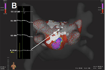
can be used to achieve the continuity of lesions (Fig. 4A).
Figure 4A Voltage base verification of linear lesions: High-density voltage map of the roof region during a redo case with previous box lesion. Note high voltage regions within the box lesion (corresponding local electrograms shown in the box)
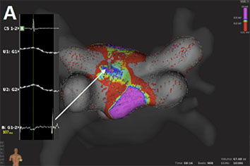
Figure 4B Voltage base verification of linear lesions: re-map of the same region after additional ablation shows elimination of high voltage potentials
To further evaluate the application of this technology, our
group has performed feasibility and efficacy studies in patients
with supraventricular tachycardias, including AV nodal reentrant
tachycardias, atrial flutter and fibrillation.63,64
The initial experience
of pulmonary vein mapping and ablation in a porcine model has
now been expanded to human atria and pulmonary vein ablation.65,66
Resent studies have provided more confirming results about the
use of the mini-basket catheter alone to sufficiently determine PV
isolation. Along with improved recording of PV potentials after
incomplete ablation, this catheter also registers “PV-like” potentials
from neighboring structures. In these cases, pacing maneuvers are
helpful to determine PVI and avoid excessive ablation.67 These results
though support the safety of the system and encourage further
clinical evaluation.
Contemporary EAMs provided the 3D navigation for AF ablation
in order to reduce radiation and improve safety, procedural time and
efficacy. Image integration and tools, like fast mapping and contactforce
feedback, act complementary towards that goal. Based on
EAMs, fractionation and voltage mapping evolved and provided the
stimulus for further developments that focused more and more on
the visualization and analysis of the myocardial electrical signals.
Advanced mapping systems emerged from the need to better
understand and ablate complex AF substrate. These efforts tried
to overcome the spatiotemporal and processing limitations of
contemporary EAMs and focused on improving the acquisition and
illustration of electrophysiological information. Innovative mapping
approaches like ripple mapping may someday allow experienced
operators to create maps of complex atrial tachycardias without
assisting experts. Mapping technics that aim to visualize AF drivers
through depiction of dominant frequency areas and characterization
of rotors or focal impulses during (intracardiac) or prior (noninvasive)
to the procedure, have shown promising results in terms
of AF termination and will be further evaluated.68 The improved
electrical signals produced by narrow-spaced catheters and the
automated high-density maps may also prove valuable for scar-based
ablation strategies.
Characterization and redefinition of AF substrate is a key-element
for future mapping systems and personalized AF ablation. Ideally,
future mapping-systems would allow visualization of the atrial
anatomy and pathophysiology, in order to individualize and monitor
lesion formation in a real-time fluoroscopy-free environment, like in
the MRI suite. 69-71
Although there is a long way ahead, it remains an
exciting time with many improvements and a bright future for AF
mapping systems.