Compass Mapping, Double Potentials, Activation Patterns Can Identify and Track Rotational Activity Sites in the Left Atrium of Humans with Persistent Atrial Fibrillation.
Donald S. Rubenstein1, Hang Yin2, Sana A. Azami3
1Greenville Health System, Greenville Health System, 701 Grove Road, Greenville, SC 29605.2Provident Sacred Heart Medical Center, 101 W 8th Ave, Spokane, WA 99204.3Greenville Health System, 701 Grove Road, Greenville, SC 29605.
Rotational circuits that occur between bipolar electrodes exhibit double potentials (DPs). It had been previously surmised that rotors could not be electrically tracked directly.
Our purpose was twofold; first, to show that the use of compass mapping, one can regionally identify rotational activity; and second, to show that by combining simultaneous compass map recordings, standard narrow-adjacent bipolar, and unipolar recordings, that specific signature recording patterns emerge that allow one to identify the accurate time, location, and path of a rotational mechanism.
This was an observational study in 20 patients with persistent atrial fibrillation in which the electrode configuration of a circular mapping catheter was changed to wide cross-circle electrode pairing (compass mapping). DPs were recorded and analyzed from 12 left atrial (LA) sites and identified electrical wavefront patterns and direction. A substudy analyzed transitions patterns with simultaneous narrow-adjacent bipolar and unipolar recordings.
Four wavefront patterns were identified: DPs, peripheral waves (PWs), distal peripheral waves and fibrillatory activity. DP wavefront patterns exhibited significantly shorter cycle lengths than PWs in 8 of 12 LA sites. Patients had 2.9± 2.1 regions that exhibited DPs. DPs of varying duration were found, few (25%) were of stable duration and location. Detailed electrical examination at the transition between a PW to a DP identified a highly consistent pattern of simultaneous reversal of activation sequence, a special form of Doppler effect for spiral waves as a rotor passes between 2 electrodes, and a ½ cycle drop-off of activation signals along the line of electrodes.
DP recordings in compass mode can provide a regional assessment for the existence of rotational activity. Simultaneous DP recordings in compass mode, narrow-adjacent bipolar, and unipolar recording provide an accurate assessment of the time, location, and path that a rotational mechanism breaches a perimeter of electrodes. Accurate time, location and path of perimeter breaches can be used to electrically track rotational mechanisms during atrial fibrillation.
Key Words : Atrial Fibrillation, Double Potentials, Compass Mapping, Rotor.
Correspondence to: Donald S. Rubenstein,
Director of Cardiovascular Research Carolina Cardiology Consultants – EP Services 877 W. Faris Road, Suite B Greenville, SC 29605
Twenty years have elapsed since the discovery that most atrial fibrillation is triggered by ectopic beats generated within the ostia of the pulmonary veins[1]. Ablation to electrically isolate these regions has provided a meaningful treatment of this arrhythmia, more so for patients with the paroxysmal than the persistent form [2]. Other ectopic sites[3] and mechanisms[4] may trigger or degenerate into atrial fibrillation. Once initiated, additional mechanisms may maintain and prolong fibrillatory activity. Controversy remains if one or multiple simultaneous sustaining factors are at play. Computational and experimental evidence has provided support for multiple rapid ectopic foci[5,6], multiple random wavelets[7], complex fractionated atrial electrograms[8,9,10] and rotors[11,12].
Reentry and rotors, both have circular paths of electrical wavefronts. However, they differ significantly when analyzing the central region of that circulation. Reentrant wavefronts move centripetally towards a center that has an unexcitable anatomic barrier or it is functionally refractory[13]. This unexcitable region prevents propagation crossing over to the opposite side that might have disrupted the continuous propagation. In contradistinction, rotor wavefronts spiral centrifugally away from a central core, called a phase singularity. There, at the center, the electrical wavefront shape progressively curves inward to a physical limit preventing advancing into the core[14]. However, since the core region is unexcited, this allows precession (meandering) to adjacent tissue that may too become briefly excitable, but unexcited. Because of the spiral nature of the rotor wavefront, as well as limitations of conduction properties, the cycle lengths measured nearest the core are shorter than adjacent tissue, thus exhibiting a Doppler effect with an approaching core[15,16,17].
Movies of action potential phase changes using voltage-sensitive dyes on in vitro animal models[11,14,18,19] along with computational algorithms[20], provided detailed analysis and description of cardiac rotor activity during fibrillatory activity. Direct electrode recordings by traditional methods of mapping in humans were deemed too complex to identify potential target areas for ablation [16,21]. Rigorous attempts have been made to recreate the electrical phase analysis (a regional display of action potential phases) in human atria. The action potential phase between electrodes and between splines of a basket catheter was approximated by mathematical interpolation[22]. Phase changes over time that exhibit a spiral movement of an electrical wavefront are considered sites of rotor activity. Ablation within these regions showed initial success for arrhythmia suppression [23,24,25], but has been met recently with far less favorable results[26,27].
Whether an electrical circuit is reentrant [28,29,30] or rotor[31], direct experimental electrical recordings near the center of rotation, or at its pivot point, consistently exhibit double potentials (DPs)[13,28]. DPs have been identified with intracellular electrodes[13], unipolar electrodes[13,[28 and bipolar electrodes[29,30]. The DPs have been confirmed to record activation on opposite sides of the electrical circular path[13],[28],[29],[30]. Closer to the center of rotation or near the site of pivot, the DPs appear evenly split [28,30]. DPs, termed inverted double split potentials, were consistently identified at rotor core sites which exhibited highly variable wavefront directions (a higher Shannon entropy,[31]). A bipolar electrode (without regard to alignment) that straddles the center of a rotational electrical mechanism will exhibit two activations (DP) recorded with each one revolution. DPs have also been recorded in various other studies and overall can identify activation on either side of a region of conduction block[32].
We hypothesized that changing the pairing of the narrow adjacent electrodes along a circular mapping catheter to that of cross-circle pairing could provide stable, regional recordings such that the operator could identify the time and place that a rotor entered the perimeter of that region. This cross-circle arrangement of bipolar electrodes creates an electrical compass. If a rotor or rotational mechanism moves toward the perimeter of a circular catheter, stable single wavefronts or peripheral waves (PWs) ought to be recorded with each rotation. However, if a rotor, that has its plane of rotation parallel to the plane of the recording catheter, meanders or precesses across the perimeter of the circular mapping catheter, then the PWs should immediately transition into recording DPs. In addition, rotor precession in and out of the compass perimeter might provide directional and possibly direct location information as to where the rotor entered and exited. Such a method might utilize direct recognition of alternating double potentials as sites of rotational activation rather than relying on proprietary computation, interpolation, and animated movies.
Twenty-two consecutive patients with symptomatic persistent atrial fibrillation (> 1week duration or required cardioversion to regain sinus rhythm) were admitted for ablation. Two patients had a prior ablation with pulmonary vein isolation (PVI). The average age of patients was 65 ± 8 years, 15 male and 7 female. The average duration of atrial fibrillation was 7.5 ± 6.2 months. Cardiac structure and function assessment show large LA diameter (4.5 ± 0.6 cm) and mild LV dysfunction (LVEF 48 ± 12 %). The average CHADS2VA2SC score was 2.3 ± 1.0. Nineteen patients had a diagnosis of hypertension, 4 patients with diabetes, and 1 patient with a prior stroke. Each patient signed a written informed consent of the research protocol that was approved by our local institutional review board. All patients underwent a transesophageal echocardiogram one day prior to procedure to exclude a left atrial thrombus. Patients remained on their prescribed oral anticoagulation without cessation. Previously prescribed antiarrhythmic drugs except amiodarone (n=9) were discontinued 5 half-lives prior to their ablation. Patients completed their procedure in the post absorptive state under general anesthesia. Standard access of catheters was performed through femoral and right internal jugular vein access. All research protocol mapping was completed prior to standard pulmonary vein (PV) isolation. PV isolation of all 4 veins was achieved in every patient. AF was terminated in 1 patient during PVI alone. All other patients underwent additional ablation lines (roof line, mitral isthmus, tricuspid isthmus, and/or appendage) with goal of achieving sinus rhythm. If AF organized to an atrial flutter or tachycardia, then this mechanism was also targeted for ablation. In another 7 patients, AF terminated with additional lines. If further mapping and ablation did not terminate into sinus rhythm, then electrical cardioversion was performed. Ablation was performed with a 3.5 mm irrigated tip catheter (Thermocool, Biosense-Webster, Diamond Bar, CA). Ablation energy used was 25 W along the posterior wall and 30-35 W elsewhere. All electrogram cycles, vector analysis was completed off-line and could not be used to help target ablation.
Compass Mapping Technique
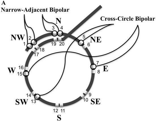
Experimentally, rotors in animals with atrial fibrillation can control a surrounding tissue area up to 5cm2[33]. A circular mapping catheter (LassoTM, Biosense Webster, Diamond Bar CA, USA) encircles an area of 3.14 cm2 and was used to systematically map, record and analyze 12 specific regions of the LA [Figure 1]. To identify and examine rotational activity with the characteristic double potentials, the bipolar electrode input configuration from the standard adjacent narrow pairing of electrodes was changed in the software electrode parameters in the recording workstation (Cardiolab, GE Medical, Milwaukee, WI, USA). An electrode was paired with the electrode directly across the circle, 8 such pairings (using electrodes 5 - 20) were made moving around the circle [Figure 2A]. [Table 1] provides the electrode pair configuration. Electrode pairs (1,2), and (3,4) remained configured as narrow pairs to provide very specific local electrical information while simultaneously recording regional wide cross-circle bipolar recordings. All recordings were made at gain of 500 with low pass and high pass filters set at 30 Hz and 500Hz
respectively. The cross-circle pairing created an electrical compass and were labelled the 8 cardinal points of a compass (N, NE, E SE, S, SW, W, and NW). Looking down the barrel of the shaft where the catheter turns perpendicular to the shaft is designated North. The East direction is designated 90 degrees moving clockwise around the compass. Sliding the thumb lever up moves the catheter downward or to the south. With a 90-degree bend toward the south, rotating the handle clockwise moves the compass to the west.
Table 1. Electrode configuration of cross-circle bipolar pairings to create compass recordings.
|
|
|
Inputs |
|
| Catheter |
Lable |
Type |
+ |
- |
| Coronary Sinus |
CS 1,2 |
Bipolar |
2 |
1 |
|
CS 3,4 |
Bipolar |
4 |
3 |
|
CS 5,6 |
Bipolar |
6 |
5 |
|
CS 7,8 |
Bipolar |
8 |
7 |
|
CS 9,10 |
Bipolar |
10 |
9 |
| Circular Mapping |
Ls 1,2 |
Narrow Bipolar |
12 |
11 |
|
Ls 3,4 |
Narrow Bipolar |
14 |
13 |
|
N 11,19 |
X-Circle Bipolar |
21 |
29 |
|
NW 9,17 |
X-Circle Bipolar |
19 |
27 |
|
W 7,15 |
X-Circle Bipolar |
17 |
25 |
|
SW 5,13 |
X-Circle Bipolar |
15 |
23 |
|
S 12,20 |
X-Circle Bipolar |
30 |
22 |
|
SE 10,18 |
X-Circle Bipolar |
28 |
20 |
|
E 8,16 |
X-Circle Bipolar |
26 |
18 |
|
NE 6,14 |
X-Circle Bipolar |
24 |
16 |
Figure 1 Left atrial sites of recording (LA). A. Posterior view of LA. Recording sites 1-8. Site 1: left lateral atrial wall; site 2: left inferior postero-lateral; site 3: left inferior postero-medial; site 4: left postero-septal; site 5: Left inferior pulmonary vein (LIPV) posterior wall ostia; site 6: Right inferior pulmonary vein (RIPV) posterior wall ostia; site 7: Left superior pulmonary vein (LSPV) posterior wall ostia; site 8: Right superior (LSPV) posterior wall ostia. B. site 9: left anterolateral adjacent to left atrial appendage (LAA); site 10: roof at LSPV; site 11: roof at RSPV; site 12: left antero-septal.
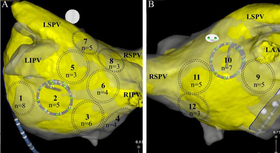
At each site, identified by dashed circles, DPs were observed by n number of patients.
Figure 2A Electrode pairing configuration to create compass-mode recording. A. Schematic of circular mapping catheter bipolar electrode configurations. Narrow-adjacent bipolar electrode pair included (1,2) and (3,4). Cross-circle bipoles are arranged in a compass-mode configuration North or N = bipolar electrode pair (11,19) , NW = bipolar electrode pair (9,17) ; W = bipolar electrode pair (7,15); SW = bipolar electrode pair (5,13); S = bipolar electrode pair (12,20); SE = bipolar electrode pair (10,18); E = bipolar electrode pair (8,16); and NE = bipolar electrode pair (6,14).
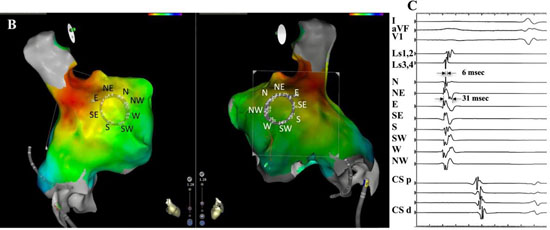
The electrode configuration setup results in a rising slope activation electrogram with an approaching electrical wavefront from that specific cardinal point direction. Compass directional information was confirmed with a 3-dimensional high density activation map that was created in sinus rhythm of the right atrium [Figure 2B,Figure 2C]. The circular mapping catheter was placed just inferior to the sinus node along the lateral wall with East electrode of the compass closest to the sinus node. Note that a large broad wavefront propagates past electrodes parallel to wavefront direction, whereas activation perpendicular to the wavefront is very short.
Figure 2B,2C. Electrode pairing configuration to create compass-mode recording.B.3-D electroanatomic map identifies sinus node region in red external perspective on left, internal perspective on right. East electrode (E) is closest to sinus node. C. Recording of electrical wavefront with circular catheter placed at lateral wall of right atrium in sinus rhythm. Top 3 recordings are surface leads 1, avF, and V1. The next two traces are recorded from narrow adjacent pairs (1,2) and (3,4). The next 8 traces record form the 8 cross-circle bipolar electrodes as configured in 2A. The last 5 traces record activation from the coronary sinus catheter (CS) from proximal(p) to distal (d). Atrial wavefront originating from sinus node moves across recording region of circular mapping catheter that records in compass mode with the E direction showing the largest, broadest activation. Perpendicular to this direction, N and S directions show smallest and narrowest activation.
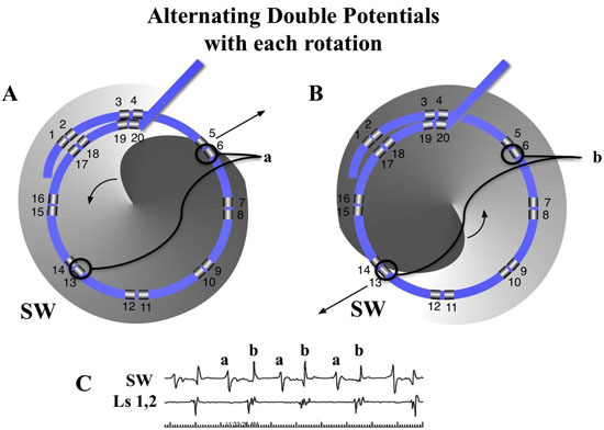
A rotational circuit, whether rotor or reentry within the perimeter of the circular mapping catheter would be expected to exhibit double potentials of alternating slope [Figure 3]. A rotational circuit outside the perimeter should result in a wavefront that passes through the perimeter with a single activation pattern that identifies the wavefront direction as it passes under the circular catheter.
Figure 3. Diagram of a counterclockwise rotor that exhibits DPs of alternating slope in compass-mode mapping. The gray spiral rotor has its advancing head at darkest gray curve. Arrow showing wavefront spiral direction) with core near the center of circular catheter with wavefront passing opposite sides of the compass. A. The wavefront spiral passes electrode 6 of the cross circle bipolar pair (6,13), SW on compass. The SW tracing shows a positive deflection. B. One half cycle later, the wavefront spiral passes the electrode 13 of the cross-circle bipolar pair (6,13). The SW tracing now shows a negative deflection since the wavefront is in the opposite direction compared to ½ cycle earlier.C. The 2 tracings below show the recordings from the SW direction with alternating DPs, while only single activation wavefront is recorded from the narrow-adjacent bipolar pair (1,2).
All patients were mapped while in atrial fibrillation prior to ablation. In one patient (patient #2), at the time of catheter entry, despite multiple aggressive pacing techniques, AF could not be induced into sustained epochs long enough to adequately map. His mapping data was not included in the analysis. Another patient (patient # 20) was in an atypical perimitral flutter at the start of the case. He was mapped while in atypical flutter and this information will likely be submitted as a case study. His data is not included along with the other 20 patients.
A LA 3-D atriography image (Philips, EP Navigator) was created in each patient just prior to induction of anesthesia. The 3-D map was merged into Carto Biosense Workstation. After transseptal puncture the circular mapping catheter was placed into the LA. The catheter was positioned at each of 12 locations of the LA. Just prior to the recording at each LA site, electrode numbers 1,2, were confirmed to be aligned with electrode 17, 18 to maintain consistent circle size. This properly oriented all electrodes as a compass. Sixty second recordings were completed from each of the LA sites. In a substudy, simultaneous unipolar and narrow adjacent bipolar electrode recordings were obtained in the last 5 patients with either jpg or mp4 files. These recordings were synchronized to the recordings on the GE workstation by placing 3-5 V-paced beats at the start and end of each one-minute epoch.
Wavefront Activation Pattern Definitions
Activation patterns of the areas mapped by the circular catheter were analyzed off-line, cycle by cycle. In [Figure 4A], and similar to what others describe[34,35], but with the addition to DPs, we designated patterns of activation as either DPs, PWs, distal peripheral waves (DSPW), or fibrillatory conduction (Fib). PWs were designated if at least 5 sequential cycles recorded a similar morphology and wavefront direction and separated between cycles with quiescent electrical activity. Cycle measurements continued until there was a sudden change in waveform morphology or direction. Cycle lengths continued to be measured for that epoch pattern if there was as shift to an adjacent compass direction sources, as what might be expected during precession (meandering) of a possible rotor core (i.e., N=> NE). CL measurements ended for this event if the shift was not to an adjacent directional vector (i.e., N=> SW). Similar to PWs, a DSPW identified regions where cyclic wavefronts had similar morphology and direction for at least 5 cycles, but at least one additional wavefront, a secondary wave, that prevented an isoelectric phase between cycles of the primary wavefront. The secondary wavefront(s) could not have a 1:1 association with the cycle lengths of the primary wavefront. Double potentials (DPs) were designated as a wavefront pattern within the region that displayed two distinct wavefront activations. The primary and secondary wavefronts maintained a 1:1 correlation of cycle lengths. To minimize chance of nonrotational causes or competing adjacent cyclic mechanisms of DPs, 5 cycles were required to be categorized as a DP. DPs were described in more detail; having alternating or same slopes, or if cardinal point activations were sequential in time or almost simultaneous (a vertical alignment in time). DPs had to be displayed in at ≥ 2 cardinal directions. Fibrillatory activity was designated for the rest of the disorganized activity recorded that did not fulfill the criteria as discussed above. Cycle lengths, number cycles, total duration, wavefront direct of each pattern were recorded over the minute. Transitions between each type of activation pattern were also tabulated.
Figure 4A. Diagram of wavefront patterns defined in Methods of compass recordings in different areas over or near a rotor. Each of the 4 recordings show the cardinal compass recordings in the top 8 traces with the next 4 traces recorded from the coronary sinus catheter (CS) from proximal (p) to distal (d). At the top left, fibrillatory (Fib) activity is seen throughout all 8 cardinal directions. At the top right, distal peripheral waves (DSPW) exhibits a cyclic pattern is seen with gradually changing morphology with additional wavefront activation between the primary cyclic activations. The bottom right shows a peripheral wave (PW) that exhibits a cyclic pattern and stable morphology with almost no activation signals between cycles. The bottom left shows the circular catheter that directly overlays a rotor and would show double potentials (DPs) in many, if not all cardinal directions.
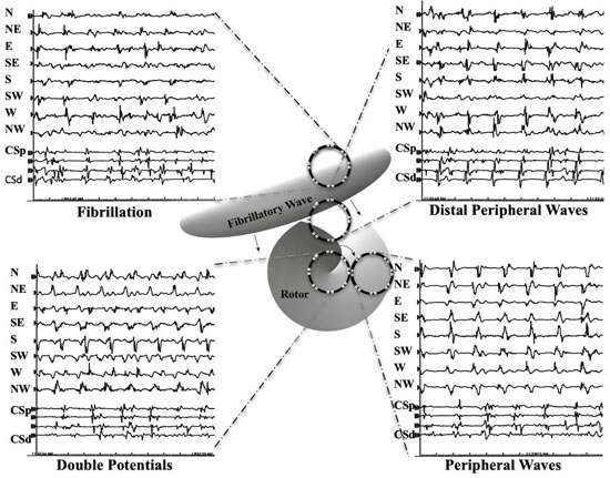
To assess inter-observer variability, all double potential sites classified by the primary investigator was reassessed by a second observer (H.Y.) All were confirmed as double potentials, six differed as to the duration of DPs, none more than 2 rotations. Final duration of these patterns was determined by mutual consensus..
Analysis of Transitions between Double Potentials and Peripheral Waves
Simultaneous unipolar, narrow bipolar, and wide cross-circle electrodes were recorded during this transition in 4 patients analyzing a total of 28 rotational events at the transition. The 5th patient had perimitral flutter. The presence of a rotational activation, parallel to the plane of endocardial surface, was defined similar to Ghoraani et al.[36]. We utilized the criteria of sequential activation along the 16 electrodes around the perimeter of the circular catheter, where head-meets-tail, and ≥2 rotations. We added further stipulation that the time gap between any 2 adjacent electrodes was ≤ 50% of the cycle length, as will be discussed below. Two separate recording systems were required to confirm DPs by compass and unipolar recording. Additional data of from the narrow adjacent bipolar recordings allowed simultaneous verification of local activity at the N and NW compass poles [Figure 2A].
Data were expressed as mean ± SEM and were compared between study groups with the use of one-way ANOVA. Probability value of P<0.05 were considered statistically significant.
Compass mapping utilizing cross-circle paired electrodes identified rotational activity whether from microreentry or rotor activity in the recognizable form of double potentials. A total of 235 sites utilizing the compass mapping method recorded regional AF out of a possible 240 sites. A stable position with good electrode contact was maintained for the 60 seconds of recording at each of the sites. Anatomic constraints, a thin flat atrial chamber, prevented stable recordings from sites 4,7,8,9 from patient # 5, site 8 from patient #8.
Distribution, Prevalence and Cycle Lengths of Wavefront Patterns
[Figure 4B] shows distribution of wavefront patterns seen at each of the 12 locations.
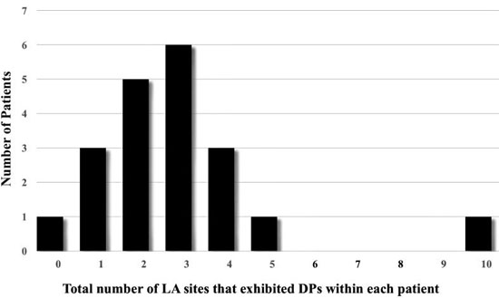
Highest percentage of DPs were located at Position #7 (9.2%), at the posterior wall just outside the left superior PV. Figure 1 shows how many patients (n) exhibited DPs at a recorded LA site. Most frequent sites exhibiting DPs included left lateral wall, roof, LSPV and RIPV (n = 8,7,5,5 respectively). A measure of local stability of the DP is the duration of epochs, for continuous number of cycles of DPs prior to transitioning to a different wavefront pattern. Duration was separated into bins of cycle #s. Most abundant were DP# 5-10 cycles (n=82), then > 20 cycles (n=38), followed by 11-15 cycles (n=37), and 16-20 cycles (n=16). Average cycle lengths (CLs) of consecutive DPs were compared between bins of 5-10 cycles (CL = 192.9 ± 34.5 msec), 11-16 cycles (CL = 182.8 ± 31.4 msec), 16-20 cycles (208.9 ± 36.7 msec) and > 20 cycles (199.3 ± 46.2 msec). Epochs exhibiting consecutive DPs of 11-15 cycles had significantly shorter CLs from epochs lasting 16-20 cycles (p =0.02) and epochs lasting longer than 20 cycles (p =0.04). Long continuous DP epochs were rare to be recorded (n=11 for 10-20 sec; n=3 for 20-30 sec; n=1 for 30-40 seconds, n=1 for > 60 seconds). Only 2 patients (Pt #19 and Pt#22) showed 2 LA sites with DPs recorded for >30 seconds. Marked variation is seen between patients in the site location, number of locations and stability. The average number of LA sites that exhibited DPs in a single patient was 2.9 ± 2.1 with a large range (0-10, [Figure 5]). Patient # 14 showed no DPs at any of the 12 LA positions. Only highly disorganized activity with only 1.8 seconds of PWs were recorded from position 1, with all other measurements showed either a DSPW pattern or Fib. At the other extreme, patient #16 had 10 of 12 LA sites exhibit DPs, with the longest total duration identified at LA site #1 for 17.8 seconds. Of interest, in the 9 patients that had been on amiodarone there was no significant difference of the cycle lengths of DPs compared to the 11 patients not exposed to amiodarone (188 ± 32 msec vs 191 ± 35 msec, respectively)
Figure 4B. Shows cumulative data wavefront patterns over 20 patients in the 12 different LA sites. LA site #7 (LSPV ostia) and site #10 (roof) showed highest percentage of DPs.
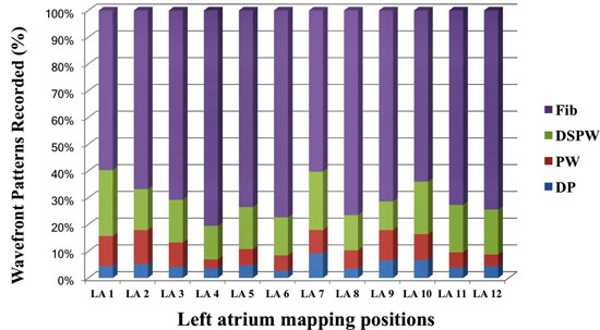
Figure 5. Number of LA sites that exhibited DPs within each patient. One patient showed no DPs at any of the 12 LA sites recorded. At the other extreme, one patient had 10 of 12 LA sites exhibit DPs. The average number of LA sites that exhibited in a patient DPs was 2.9 ± 2.1.
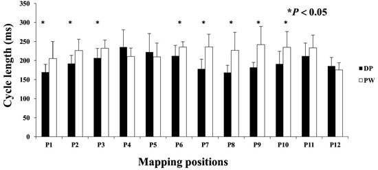
Cycle lengths of Waveform Patterns and Evidence for Rotor Doppler Effect.
Many DPs were preceded and or followed by a short period of a PW pattern. Measuring CL at this transition commonly exhibited a shortening of CLs, or Doppler effect on the compass recordings until DPs were manifest. The opposite was noted moving from DPs to PW. The CL of DP wavefront patterns were evaluated in a matched pair comparison to the CL of PWs from the same LA site [Figure 6]. Eight of 12 LA sites showed a significantly shorter CL for DPs compared to PWs. DP cycle lengths did not show a significant difference at any of the 12 LA sites when compared to DSPW.
Figure 6. DPs and association with Doppler Effect. Compass mode mapping exhibits a PW across the region of recording, the CL shortens as a rotational mechanisms precess into that region. Each LA site was matched paired with PW to DPs. DPs showed significantly shorter CL compared to PWs at LA sites 1,2,3,6,7,8,9,and 10.
Recording the transitions between DPs and PWs were most instructive. It might be expected that an approaching rotor prepares or clears the tissue ahead of it by organizing it into PWs prior to precessing into that region. In the 173 recordings of DPs, there was a transition from a PW pattern (n=26, 15.0%), DSPW (n=88, 50.9%)and Fib (n=59, 34.1%). Once in DP, there was a transition to PW (n=27, 15.6%), DSPW (n=69, 39.9%) and Fib (n=77, 44.5%).
In Depth Analysis of DP Transitions and New Relative Doppler Effect Physiology
Perimeter breech, Activation Sequence Reversal Compression and Expansion Doppler Effects
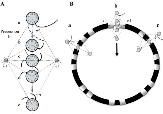
Transitions to and from DPs and PWs were analyzed with simultaneous recordings in compass mode, narrow-adjacent bipolar and unipolar recordings. A diagram is presented first to demonstrate hypothetical geometric and time dependent changes of electrode recordings as a rotor passes between a pair of electrodes [Figure 7A]. A rotor, represented as a clock hand moving clockwise lies just outside the perimeter of the circular catheter. The wavefront generated from the rotor crosses the two electrodes (e2 and then e1) at times 5 and 7 o’clock respectively. As the rotor moves along a path that bisects e1 and e2. The timing of activation at these electrodes moves in opposite direction. The e2 activation signal occurs progressively earlier in the rotation cycle, while the e1 activation signal occurs progressively later. The time lapse between activation signals from e2 and e1 lengthens. If the rotor were to sit at the midpoint between the 2 electrodes, then the time separation between the 2 electrodes would be ½ of a full rotation. If e1 and e2 are electrodes of a bipolar recording, then the activation recordings would result in alternating double potentials (movie1, and [Figure 7B]). This leads to an important finding that the narrow-adjacent bipolar recordings can detect crossing the perimeter by a transient DP in that specific pair just as the cross-circle pairing detects that a rotor has moved within the perimeter. Importantly, once the rotor has moved within the perimeter of the circle, the time gap between the e1 and e2 electrodes would be less than ½ the CL.
Figure 7. Diagram of differential Doppler effects on electrodes with precession past electrodes. A. A rotor diagrammed as a clock hand circulating clockwise moves on a path that bisects electrode 1 and 2. Electrode 2 is on the side of the rotor which the wavefronts are moving forward, parallel to the precession path. Electrode 1 is on the other side of the rotor which the wavefronts are also parallel to the path of precession but in the opposite, or backward direction. Initially (position a), a spiral wave will transmit a wavefront signal at electrode 2 at 5 o’clock followed shortly by the wavefront signal reaching electrode 1 at 7 o’clock. A moment later (position b), with the rotor closer to the electrodes, the wavefront reaches electrode 2, earlier in time, at 4 o’clock (Doppler compression with a shorter CL), while reaching electrode 1, later in time, at 8 o’clock (Doppler expansion with a longer CL). When the rotor reaches a point directly between electrodes 1 and 2, the wavefront reaches electrode 2 at 3 o’clock and then electrode 1, a full ½ cycle later, at 9 o’clock. If the rotor were to stay at this position, DPs that are fairly equally separated in time would be expected, (see Movie 1). The process continues as the rotor reaches position d and e. When reaching these positions there is a reversal of sequence, activation at electrode 1 followed shortly by activation at electrode 2. B. Diagram of three paths that a rotor can breach the perimeter of the circular catheter, between 2 pairs of narrow-adjacent bipolar electrodes (a), between 2 electrodes of a narrow-adjacent pair (b), or directly under an electrode (c).
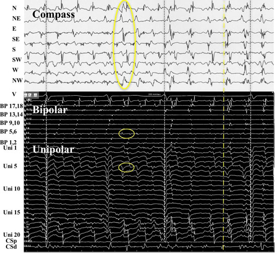
In patient #18, at LA position #7, rotational activity was noted to be slowly transitioning from the perimeter with DPs on all 3 forms of recordings (compass, narrow-adjacent bipolar, and unipolar, [Figure 8] to a position outside of the compass, generating a PW [Figure 8C]. The PW, identified by the vertical yellow dashed line on the right, shows a wavefront that has earliest activation at electrodes 5,6 at the NE compass point. Two cycles earlier than the yellow line, the largest gap in time is seen on unipolar 6. Note the drop of ½ of the signals from electrodes 6 through 20. This position site as seen in[Figure 8AandFigure 8D], was incorporated within the ablation line that circumnavigated the left PVs. Isolation was achieved, Afib persisted. Just prior to completion of the right PV isolation line, AF terminated. This patient has remained arrhythmia free for 22 months. Our simulation of the activation sequence of a rotor is taken further and breaches a line of electrodes or a perimeter of electrodes around a circular catheter (Movie 2 and Movie 3). This slow-motion identifies an expected pattern of activity that would be specific to a rotor or any rotational mechanisms that moves completely to the other side of the recording line. If a rotor close to the line of electrodes moves along a path towards the midpoint of 2 electrodes, then relative Doppler compression of wavefronts are expected on the electrode receiving the forward moving waves that are parallel to this path. A relative Doppler expansion of wavefronts are expected on the second electrode that is on the opposite side of the rotor. This second electrode receives the backward moving wavefronts relative to the precession direction. At this moment of transition a PW with mostly vertical alignment of activation signals becomes slanted or sequential in alignment where head-meets-tail. That transition, that breach, occurs at the site between the 2 electrodes that exhibit maximal Doppler compression and maximal expansion of wavefronts. This occurs at the moment that activation sequence reverses in direction (movie2 and movie3). Whether precession occurs past a line of electrodes, or along the perimeter of a circle, that transition pattern of Doppler compression and expansion is the same. The progressive delay in activation at the 2nd electrode along with the simultaneous changes in all the other electrodes along the line, results in a unique pattern of activation change that we label as the ½ cycle drop-off. This position and moment in time of sequence reversal, puts a very specific location of the center of rotation. The ½ cycle drop-off would be unique to a rotor or a microreentrant mechanism, since it requires the entire circular path to have crossed the line between the 2 electrodes.
Figure 8. Rotational mechanism at perimeter of circular catheter. A. 3-D anatomical map with transparent position of circular catheter placed at LA site 7 in patient #18. B. Top 2 tracings show surface leads I and V1. Next 10 tracings show narrow-adjacent bipolar electrode recordings around circular catheter, then unipolar electrodes followed by coronary sinus (CS) proximal (p) and distal (d). The last trace shows recording from CS catheter. Yellow circle shows position of electrode 5 at site of DPs as seen throughout recording of bipolar pair (5,6). C. Simultaneous recordings at LA site #7 from top: compass map (top 8 recordings), V1 surface recording used to synchronize all recordings with grey-white dashed lines, middle: narrow-adjacent bipolar (middle BP pair 10 recordings), unipolar (bottom Uni 20 recordings) around catheter and then coronary sinus (CS) proximal (p) and distal (d). The yellow circles show simultaneous DPs in unipolar 5, narrow-adjacent bipolar 5,6, and throughout compass recordings. The yellow dashed line shows the rotational mechanism precessing out away from perimeter of circular catheter as DP pattern switched to PW on compass, bipolar, and unipolar recordings, while the sequential activation gives way to a more vertical alignment. Note that location is corroborated by the largest amplitude, earliest positive deflection occurs at NE – E direction which is exactly where electrode pairs (5,6) reside. D. Superimposed ablation lesions compared to location of relatively stationary rotational mechanism. Electrode 5 is well within the lesion set to isolate the left PVs.
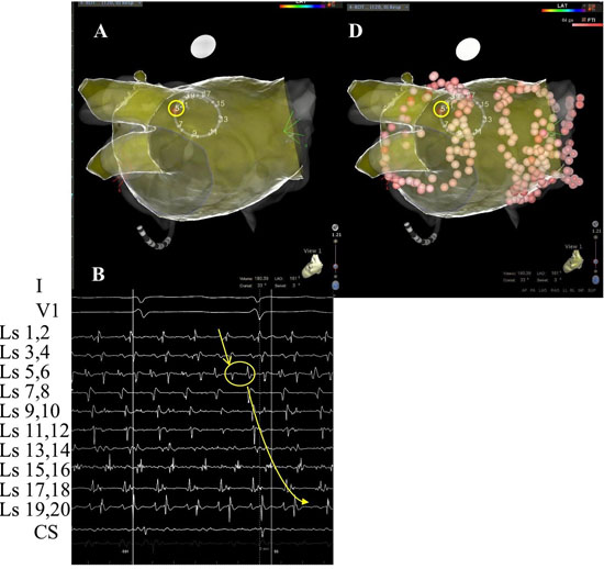
Figure 8B.
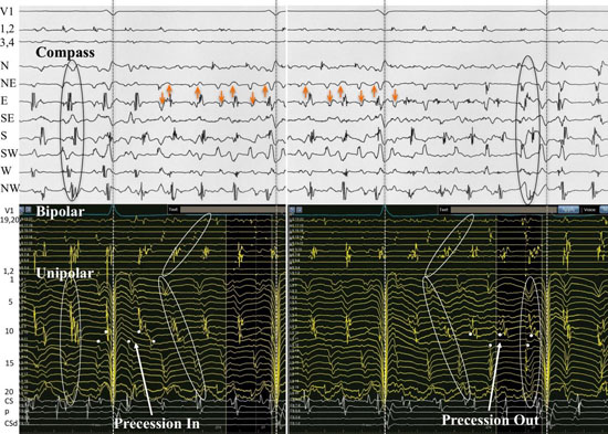
Recordings from patient #21 at position 9 [Figure 9AandFigure 9B] shows simultaneous compass, narrow-adjacent bipolar and unipolar recordings of a transition from a PW to DP and then back to PW. At the moment of wavefront pattern transition occurs in compass mode, the unipolar activation pattern shows the Doppler compression and expansion at poles 12 and 11 respectively, while the same bipolar pair (11,12) exhibit DPs. The ½ cycle drop-off occurs above electrode 10. The opposite transition occurs with precession out from the circle. This pattern repeated a total of 5 times during the 1 minute of recording.
Figure 9. A rotor precessing in and out of a circular perimeter of electrodes. Simultaneous methods of recordings were performed at LA site #9 from patient # 21. From top: Surface lead V1, narrow-adjacent bipolar pair 1,2 and 3,4, compass recordings (next 8 recordings), narrow-adjacent bipolar pairing 1-20 electrodes, unipolar recordings 1-20, and coronary sinus (CS) tracings proximal (p) to distal (d). Initial wavefront pattern is a PW on compass recordings (black vertical oval) with fairly vertical alignment of bipolar and unipolar recordings. As rotor precesses passed the perimeter, alternating DPs (gold arrows) develop throughout compass recordings while a sequential alignment (slanted white circles), head-meets-tail of narrow-adjacent bipolar and unipolar recordings. A ½ cycle drop off occurs between electrodes 11 and 12. A Doppler compression of wavefronts occur at electrode 12, while there is a Doppler expansion at electrode 11. White dots show the moment that the 1/2 cycle drop off occurs when the vertical alignment switches to sequential alignment and reversal of activation sequence. The narrow-adjacent bipolar recording shows a DP as the rotor passes between the 2 electrodes. The right-hand portion of the figure shows the opposite movement of the rotor passing between electrode 11 and 12. The rotor continues to spin with the same direction. Sequential activation with a slanted head-meets-tail alignment are identified by white slanted circles. As expected the rotor precessing in the opposite direction of between the same electrode pair exhibits a Doppler compression of wavefronts at electrode number 11 while electrode 12 receives a Doppler expansion of wavefronts (white dots). A DP appears at the narrow adjacent bipolar recording of 11,12 at the moment of ½ cycle drop off occurs and when the PW pattern appears on the compass recordings (black vertical oval). Grey to white dashed lines synchronize unipolars to compass recordings.
Back and Forth Rotor Precession
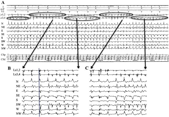
Even though we did not have simultaneous unipolar recording of patient #16, the simultaneous narrow-adjacent bipolar recordings from the free end of the circular catheter (Ls1,2) and (Ls3,4) were available to observe. A special transition occurred to and from PW and DP on the compass and ultimately provided a rare look at rotor precession ([Figure 10A,Figure 10B,and Figure 10C]). The simultaneous DPs at the narrow-adjacent pair Ls3,4 coincided with the DPs on the compass in the wider cross-circle (N-NE direction) which is orthogonal to Ls3,4. When the DPs move (presumably the site of the rotor core) to narrow-adjacent pair Ls1,2, the DPs in the compass mode record a transition of the wavefront pattern to PWs. The rotor moved along the line of the catheter, back and forth between narrow-adjacent pairs Ls1,2 and Ls3,4 and exhibited twelve transitions in the first twenty-three seconds of recording, each time coinciding with simultaneous transitions in the compass. The repetitive electrical activation pattern was confirmatory that a rotor precessed back and forth at this location. Bipolar pair Ls1,2 must lie just exterior to the perimeter since when DPs occurred here at this narrow-adjacent pair, only PWs were being recorded on the compass. The equally separated DPs recorded from Ls1,2 are consistent with a rotor just outside the perimeter of the compass. The compass mode recording provides location verification that the rotor exists very close to the perimeter (maximal and earliest positive deflection at the N direction) exactly where these narrow-adjacent pairs of electrodes are located. As soon as the DPs move to bipolar pair Ls3,4 there is a simultaneous switch to DPs within the compass and loss of DPs at bipolar pair Ls1,2. Each transition showed a gain of DPs at one bipolar pair with a simultaneous loss of DPs at the other bipolar pair. This provided a critical form of proof of rotor activity without need to annihilate the rotor. In addition to the remarkable repetitive recording patterns, this recording allowed a unique opportunity to analyze the behavior, morphology and patterns of a rotor (Fig 10B and 10C). The electrogram recordings exhibited discreet DPs while at other times, there was a transition to one component of the DP being more uniform while the other became highly fractionated as in complex fractionated atrial electrograms (CFAE). Since the complexity appeared to be asymmetric, far more complex on one of the double potential components, it suggested that the rotor core might be directly beneath just one of the electrodes. If the rotor is in fact moving down the line of electrodes, then the core would be recorded passing beneath. The multicomponent complex fractionated electrogram exists throughout this recording and meets criteria to be considered as a CFAE[9]. CFAEs may be nonspecific but no one knows if that specificity increases when the CFAE is one component of a DP.
Figure 10. Precession of a rotor along a line of electrodes passing back and forth at perimeter at LA site #7 from patient #16. A. Recordings from the top are surface leads I, avF and V1, narrow adjacent bipolar electrode pairs Ls1,2 and Ls 3,4, Compass recordings, and coronary sinus (CS) proximal (p) to distal (d). Simultaneous narrow-adjacent pair of electrodes record DPs between electrode pair Ls1,2 with immediate shift to pair Ls3,4. Each time that DPs appears (top ovals) at bipolar pair Ls1,2, a PW is observed on the compass. As the rotor precesses to the bipolar electrode pair Ls3,4 as seen at the bottom ovals, a DP wavefront pattern is seen throughout compass recordings consistent with rotor within the perimeter. B,C. Expanded version of two of these transitions are seen below. Electrode pairs Ls1,2 and Ls3,4 are the free end the circular catheter. Wavefront pattern transitions between DP and PW occurred 12 times in 23 seconds. At each moment of transition, there was a simultaneous transition in which the local DP recorded, switched back and forth between narrow-adjacent pair Ls1,2 and Ls3,4. This observation can be explained by electrode pair Ls3,4 at a position just within the perimeter of the cross-circle pairs, while the electrode pair Ls1,2 lies just outside the perimeter. Further evidence of rotor at this site is the simultaneous PW pattern which exhibits largest amplitude, broadest span and earliest positive deflection at the North cardinal point where bipolar electrode pair Ls3,4 resides.
Of the 28 rotational events (56 transitions) identified by sequential activation around the 16 electrodes, 26 had both precession into and out of a PW pattern. Each of the other 2 events had sequential activation preceded by fibrillatory wavefront patterns. Once in a sequential activation, the wavefront pattern transitioned to a PW. 54 out of 56 transitions (96%) each showed the ½ cycle drop off pattern. Seven of these epochs were less than the 5 cycles to be considered by our definition of a DP pattern on compass mapping. An additional 2 events had sequential activation but were at the perimeter with sequential activation (i.e. [Figure 8Band[Figure 8D]), with 50% of CL between 2 adjacent electrodes with DPs noted at that electrode location (both unipolar and narrow-adjacent bipolar). 16 of the 43 DP epochs (either sequential, n=22; or vertically aligned, n=21) recorded in compass mode had either a sequential unipolar activation or a perimeter activation pattern for a positive predictive value of 37%. Sequential activation of DPs in compass-mode (less than a 50% time gap between all cardinal directions) was seen in 22 of the compass-mode recordings resulting in a positive predictive value of 73% of sequential unipolar activation. None of the vertically aligned DPs in compass mode showed sequential activation in the unipolar recordings
Ablation data is presented anecdotally. This was a pilot observational study to determine usefulness of DPs in compass mode and in typical narrow adjacent electrode separation to determine regions of rotational activity and to identify electrical patterns of activation directly that will be useful in newer mapping systems. DP data was evaluated retrospectively and assessed off-line. Ablation at sites of rotor activity was only due to it being discovered that that site was incorporated into ablation lines. Patient 18 had the stable rotor at the posterior wall adjacent to the ostia of the LSPV as discussed above. Eight of 20 patients had AF terminate during ablation of PVs with or without additional lines. Fifteen patients are arrhythmia free, five of whom required a 2nd procedure, and one while on additional flecainide. The other five patients with recurrence opted for AVNode ablation with permanent pacemaker implantation.
Long term successful treatment of persistent AF by ablation remains elusive. If ablation is to be effective, then improved mapping methods, identification of maintenance mechanisms, and ablation site strategies must all become more accurate. It has been previously suggested that direct electrically mapping of rotors would be nearly impossible due to meandering of the rotating core along with constant changing of electrical waveforms. It has long been known that a rotational mechanism that has a pivot point or its center of rotation between 2 electrodes will exhibit DPs[28,29]. Therefore, we used the premise that by setting up a perimeter of electrodes, that specific patterned activation wavefronts could detect when the center of rotation crossed the perimeter (a perimeter breach). Important detailed analysis along the perimeter can specifically locate the core at the time of the breach.
Time, location, and path are essentials to proper targeting. In addition to rotational mechanisms, DPs can occur if the wavefront is split at a pivot point such as at the end of a scar. However, there are important activation characteristics of DPs that should allow the operator to discriminate whether the cause of the DPs is from a rotational mechanism versus a scar.
Assessing techniques with other standard mapping catheters, it was surmised that only non-meandering rotors could be localized in the mere happenstance that the catheter lay directly over the rotor[37]. A rotational wavefront, with its center of rotation between a bipolar electrode pair, will record DPs whether the mechanism is reentry or rotor[28,29,31]. DPs would be expected to be recorded at a pivot point, or surrounding the center of rotation in any 3-dimensional plane. Some rotors can electrically control local tissue with stable centrifugal spiral waves having diameters as great as 6 cm[34]. Modification of bipolar electrode pairing to a cross-circle arrangement provides an immediate compass-like assessment of a 3 cm2 region. A rotational mechanism with its center within the perimeter would be expected to exhibit DPs around the compass and potentially alert the operator to look more closely at this region for specific activation patterns that identify rotor location. We set out to prove that one could identify not only regionally locations of rotational activity, but that specific reproducible patterns of activation unlocked the puzzle as to precisely where and when a rotor moves passed a line of electrodes.
We studied LA sites to detect DPs within 12 specific locations. The circular catheter provided consistency in electrode contact stability, reliable electrode separation distances (regardless of LA size), and ability to record from nearly all areas of the LA. Clearly, we were disadvantaged by the inability to record from all regions of the LA simultaneously. Analyzing the 1 minute epochs, cycle by cycle, allowed us to observe patterns of activation and precession that were consistent with other investigator descriptions[34,35]. Presence or absence of DPs provided statistical information regarding that specific region. However, patient # 6 provided some important insight into the duration of recordings. In the minute that we recorded from LA position #8, the entire minute exhibited only fibrillatory activity. Just prior to moving the catheter to the next LA position, DPs emerged and a full second minute was recorded, but not included in the statistical analysis. In that 2nd minute, seven epochs of DPs were recorded ranging from 866 msec to 9152 msec (5 to 49 rotations). DPs, PWs, DSPWs and Fib were recorded representing 38.4 %, 5.6%,5.5%, 50.5% respectively. This begs the question then, how much time is adequate to record? Studies using different methods, different catheter types, utilized different epochs of analysis. Only 2.5 seconds were recorded from sites in a circular catheter study of activation sequence[36], 4 seconds by basket catheter use in CFAE[24], 5 seconds in a point by point catheter tip measurement for dominant frequency[17,38], 8 seconds in a Pentaray study of Shannon entropy[31], 10 seconds in an epicardial high density electrode plaque[34], 1 minute in basket catheter phase map[39], and 5 minutes using a spiral catheter to measure CFAE[17]. We clearly have an incomplete and inconsistent picture of persistent afib.
Results from the substudy identified a new physiologic form of the Doppler effect that is unique for wavefronts emitted from rotors. Typically a Doppler effect is defined as the change in frequency or wavelength noted when the source of the wave is moving relative to the observer[40]. However, in this human physiological example of a source emitting a cyclic wavefront, the wavefront is not a simple periodic wave transmitted radially, but it is a moving rotor core emitting a spiral wave. The observers, in this case, are two adjacent electrodes along the perimeter of a circular catheter, and the core of the spiral wave approaches and moves along a path between them. Initially, with the core near the circular catheter, the compass recording mode identifies a PW that is transmitted across the circle. As the rotor core moves along a path directly between the 2 consecutive electrodes, both sense the activation wavefront nearly simultaneously with e2 slightly ahead of e1 (position a and b of Figure 7A). In the explanatory figure 7, movie numbers 2 and 3, and actual real human recordings in [Figure 8andFigure 9], the changes in CL as recorded by two electrodes as the rotor approaches and moves passed, depend upon which side of the rotor that the electrode sits. The electrode on the side of the rotor that receives the activation of forward moving wavefronts (e2 in Figure 7A), there is a decrease in the CL, a higher frequency, as the rotor approaches, as would be expected in a typical Doppler effect.
However, on the other side of the rotor (where e1 sits in[Figure 7A]), the wavefronts are moving less directly forward and therefore as the rotor approaches, it takes progressively longer for each subsequent wavefront to reach e1 than it does to reach e2. Thus, the Doppler effect at e1 is less than e2. We believe this is first description of this special form of Doppler effect and is critical to the understanding of activation sequence changes observed with a moving rotor passed stationary electrodes. The change in timing of activation between these 2 electrodes is a result dependent upon the electrode’s relative position to the spiral wave. The electrode receiving the forward moving wavefronts as the core moves forward exhibits a relative compression (a shorter frequency) of cycle lengths compared to the electrode on the opposite side of the core which exhibits a relative expansion (a longer frequency) of cycle lengths. At the moment that the rotor core is directly between the 2 electrodes, at the perimeter, the wavefronts are moving in directly opposite directions. These wavefronts are separated in time by one half of the cycle length, creating the DP when the e1 and e2 are configured in a bipolar mode. As the core continues moving passed e1 and e2, to a position within the circle of the electrodes, then there is an immediate reversal in activation sequence (e1 ahead of e2). To reverse activation sequence there is a loss of activation in ½ the electrodes (½ cycle drop-off, movies 2, 3, and [Figure 9]).
In a simplified overall view, the compass-mode recordings show when a rotor moves from outside the perimeter of the circular catheter to somewhere within the perimeter by the transition from a PW pattern of activation to sequential DPs around the compass points. The unipolar and narrow-adjacent bipolar electrodes identify where specifically that the rotor core passes between 2 electrodes along the perimeter. DPs are exhibited between only one set of narrow-adjacent pairs along the perimeter at the moment the core is between these 2 electrodes (i.e., e1 and e2 of [Figure 7A,Figure 8]). A moment later when the core is inside the perimeter, DPs are then exhibited when looking at a bipolar pair of electrodes that is perpendicular or cross circle in compass-mode.
The relative Doppler compression-expansion pattern along with the ½ cycle drop-off pattern at the time of reversal of activation sequence was observed in 54 of 56 unipolar transitions (96%) from either the vertical time alignment of activation into sequential activation around the circle (PW to DP in compass mode) or transition from unipolar sequential activation into vertical activation (PW to DP in compass mode). The electrode positions where there is a Doppler compression immediately adjacent to the electrode that exhibits the Doppler expansion is also the electrode site that exhibits the ½ cycle drop-off when looking at all the electrodes around the perimeter. This is the site exactly where the rotor just passed. If a rotational mechanism exists with its plane of rotation parallel to the endocardial surface and the circular recording catheter, then there are 3 pathways that the rotational mechanism may enter the perimeter of the compass; between 2 electrodes of a narrow-adjacent bipolar pair; between 2 pairs of adjacent pairs (pattern similar to unipolar recordings of all electrodes around circle); or directly under an electrode. We showed examples in actual human recording of all 3 transitions across the perimeter. In a previous study[36], the authors also used a circular catheter and confirmed that sequential activation around the circle of electrodes was indicative of rotor activity within the circle. Although not discussed, it should be noted at the transitions into sequential activation around the circular catheter, the ½ cycle drop-off described here, also can be observed in their Figures 3,4, and 5. These details become very important in distinguishing sources and patterns of DPs.
Other than rotational wavefronts, DPs can be observed when recording over scars. [Figure 11] shows diagrammatically that an electrical wavefront can move one of two ways around a scar. First, the wavefront could split into 2 waves, one with slight delay and travel on both sides of the scar. Second, the wavefront could turn at the pivot point at the end of the scar and move backwards along the opposite side of the scar. Both would cause delay in activation at opposite sides of compass catheter, creating DPs.
Figure 11. Wave propagation near a scar. A. A circular mapping catheter lays across a scar (stippled line) on atrial tissue. The scar crosses between electrodes e1 and e2. The electrical wavefront splits into two wavefronts at the end of the scar at pivot point 2. The wavefront delay underneath the scar would result in DPs between the top and bottom half of the compass. B. The electrical wavefront passes along one side of the scar and pivots around the other end of the scar P1, circling back underneath the scar. This too would result in DPs recorded in compass mode.
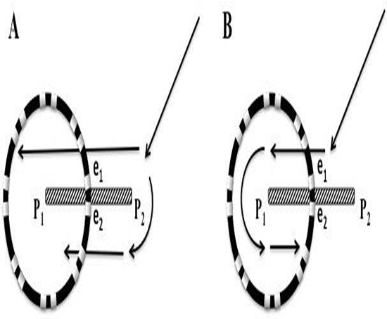
Important differences are immediately evident when comparing DPs from a continuous rotor with a precessing core versus a scar. First, the scar is immobile and the DP pattern would therefore be fairly uniform over time. DPs created by a delay of activation along one side of a scar [Figure 11A], would be expected to be more vertically aligned in time, not sequential around the circle. In either example of [Figure 11], there would be no transition from PW to DPs, there would be no reversal of activations sequence, no transient DP at the perimeter breach site, and no ½ cycle drop-off pattern when observing all the electrodes. In addition, recordings along scars typically have either little or no voltage. Therefore, recordings of DPs from a rotor moving along a line of narrow-adjacent bipolar electrodes (as seen in Figure 10) might never occur because of a scar. DPs from a scar might be confused from DPs from a rotor that is anchored to one particular spot. However, there would still be an expected shorter CL as one approaches the core of a rotor. One would not see a change in CL as one approached a scar. Lastly, the DPs of a rotor even if stationary, would be sequential activation around the cardinal compass points, and the time separation between activation between any 2 adjacent cardinal direction or any 2 consecutive unipolar electrode must be less than 50% of the CL. Only at the perimeter, the wavefront has 1/2 rotation through all the electrodes and the 2nd half of the rotation moves all the way around until reaching the perimeter of electrodes once again. A reentrant circuit around a scar that traverses one part of the circular catheter may show similar DPs to that of a rotor. No Doppler effect would be expected. Whether mechanism is reentrant or rotor in this case is moot, as this region of tissue would be a target for ablation.
If we assume that sequential unipolar activation, head meets tail with a time gap of ≤ 50% of the CL is indicative of a rotational mechanism, then the DPs recorded in compass mode of any alignment (vertical or sequential) only had a positive predictive value (PPV) of 37%. Separating out the vertically aligned DPs, the PPV of DPs observed sequentially around the compass points improved to 73%. Importantly, none of the vertically aligned DPs in compass mode showed unipolar sequential activation. Thus, vertically aligned DPs in compass mode recording may be a result of wave propagation around a scar, or possibly even from a rotor that its plane of rotation is perpendicular to the tissue recording plane. The fact that a rotor core could be recorded moving down a line of electrodes [Figure 10] with DPs only observed between 1 bipolar pair separated by only 2 mm, suggests that the rotor core was < 2mm. Average atrial muscle thickness has been measured by MRI at 2.37±0.74 mm [41], so all rotors might not have a rotational plane that is parallel to the endocardial surface, and in theory, may even change axis or flip poles over time.
We did not statistically study CFAE sites, but we repeatedly observed their appearance in our study. CFAEs have been recorded at sites of wavefront curvature (pivot points), but may also occur in regions of slow conduction[42]. CFAEs were studied with Shannon entropy [31], during phase mapping[24], and epicardial mapping[34], none of which showed close correlation with sites thought to be important to target for ablation. As was observed in several patients, CFAE was often seen as one of the components of DPs in the narrow-adjacent bipolar electrode pair at the precession breach site, with a rare continuous recording at a breach site in patient #16 Figure 10. The fact that the CFAE migrated as a component of the DP is especially interesting. CFAEs also appeared in other electrode recordings at a significant distance from the breach site. A future study might assess whether CFAE as a component of a DP to be a more specific signature of a rotor core.
The time perspective of direct electrical rotational epochs however should not be lost when comparing these results to indirect interpolated phase mapping. Narayan et al. [24], has described rotors as being stable lasting at least tens of minutes and precessing within regions of 2-3 cm2. The circular catheter used in our study has a 3 cm2 area of coverage. Detailed off-line compass recordings, cycle by cycle, and more refined narrow-adjacent bipolar and unipolar recordings found long running epochs but these were quite rare. Only 5 patients (25%) showed epochs lasting 20 seconds or greater. Yet, similar to their study, we found between 2-3 LA (2.9%) sites per patient that showed evidence of rotational activity. However only 2 patients (10%) had DPs recorded for > 30 seconds, and only 1 patient exhibited DPs for the entire minute. Our findings of very frequent short rotational epochs are consistent with more recent investigations[34,35,36,43].
We used a circular mapping catheter, but we expect than any shape with a perimeter of electrodes would show the same activation pattern changes as a rotor passes from one side to the other. With all 3 tracking requirements (time, position, and path) met, new recording, tracking and targeting strategies can now be devised. Scaling up with automated software using simultaneous highly dense electrode maps might now provide the ability to identify and track directly (without interpolation) rotor locations over longer times.Three important phases of a rotor life-cycle could be investigated as possible customized target sites of ablation. On-line tracking should provide the ability to precisely identify unique or common atrial tissue sites that spawn rotors (sites of wavefront vortex shedding), common paths of meandering or precession, or common sites of anchoring. Targeting any one or a combination of these 3 sites might improve arrhythmia-free duration endpoints. Scaling up with automated software using simultaneous highly dense electrode maps for longer recording periods for on-line analysis that can recognize DPs, reversal of activation patterns, migration of DPs, will require significant software development and testing. Once completed, direct electrical mapping and ablation studies could be compared in a randomized study against interpolation mapping and ablation methods.
DPs were examined from cross-circle compass mode, narrow-adjacent bipolar, and unipolar recordings focusing on rotational mechanisms and transition pattern of activation. We only recorded from the LA, therefore we do not know if longer duration rotor activity from the right atrium would have impacted the prevalence of rotor sites. We did not analyze for possible ectopic sites of activation and this would have been recorded as PWs. Whether PW was a result of an ectopic focus or from a nearby rotor will be a subject of future investigations. We utilized a circular catheter that we purposely kept the same dimensions to provide consistent cardinal directions of a compass. A rotor with a smaller radius of wavefronts that morphed into fibrillatory activity would have been detected as a DSPW. A smaller size catheter may have improved detection, but we would have lost tissue coverage. We did not record simultaneously from all left atrial sites, it is not known if this would result in under or overestimation of rotor activity. Finally, our recording figures, as in all publications, were selected with the least noise, best amplitudes. There is a selection bias on these figures by all authors to convey their clear thoughts and results to the reader. Therefore, in real-time, the recording of short epochs, pattern recognition, perimeter breaches, all would be present and gone, literally in the blink of an eye. Reliance on current computer interpolating algorithms may be premature. Mapping and targeting AF remains at its infancy.
Our methods of studying DPs provided the ability to have stable local contact, high electrode resolution, and consistent shape, that allowed us to recognize electrical patterns of rotational mechanisms during atrial fibrillation. These recordings, we believe, are the first to identify specific electrical patterns of rotor activity and behavior as it breaches a line or perimeter of electrodes. By our findings, we also believe that now have the fundamental tools to electrically map and track rotor activity directly without need for interpolation. This study was conducted using standard recording methods but it required very time-consuming off-line analysis. Technological improvements with better high dense electrode resolution will be needed to create higher quality, efficient mapping techniques. Since stable rotors of long duration, limited precession appears to be rare (5-25%), then at the current state of technology, the compass map method might be used to quickly survey the atrium. Compass mapping might allow for time and cost efficient targeting of the more rare low-hanging fruit without need of proprietary software and basket catheters.
The frequent short duration epochs of rotational activity with precession requires a paradigm shift in thought, investigation, and ablation strategies. Without more detailed mapping, our current methods used for ablation in patients with persistent AF is more a “whac-a-moleTM” technique on a klinkoTM game. Now with the building blocks to electrically record directly rotor location and path by using the electrodes as sensors of a perimeter breach, specific customized maps could be created. More importantly, the life-cycle of a rotor could now be assessed from the time of spawning of vortex shedding to migration, to anchoring, to its final demise. In 2 patients of detailed unipolar and narrow-adjacent bipolar recordings, sequential activation was not preceded by precession from a PW and appeared to emerge from fibrillation. If this was a site of vortex shedding, then a preceding Fib recording directly into sequential activation, head-meets-tail, might identify common sites of rotor births. Ablation sites of regions of vortex shedding might be as important as the ablation lines used to isolate sites of ectopic impulses, or sites of rotor anchoring. In addition, studies are needed desperately to evaluate directly different ablation patterns on atrial tissue substrate and its effect on rotor precession [44]. The goal of ablation should be to optimize conduction with least destruction.
Movie 1. Slow motion activation patterns as a rotor is positioned directly on the perimeter between a narrow-adjacent pair of electrodes. Two activations occur with each rotation, creating double potentials.
Please Click here for "Movie 1"
Movie 2. Slow motion activation patterns of a rotor precessing passed a line of electrodes.
Doppler compression, expansion, reversal of activation and the ½ cycle drop off.
Please Click here for "Movie 2"
Movie 3. Slow motion activation patterns of a rotor precessing passed a perimeter of electrodes.
Doppler compression, expansion, reversal of activation and the ½ cycle drop off.
Please Click here for "Movie 3"
D S Rubenstein received a consulting a fee from BioSense Webster.