Intracardiac ECHO Integration with Three
Dimensional Mapping: Role in AF Ablation
Yaariv Khaykin,MD1, Allan Skanes, MD2, Zaev A. Wulffhart, MD1, Lorne Gula, MD2, Bonnie Whaley, CVT1, Richard Oosthuizen1, Catherine Seabrook, RN1, Marianne Beardsall, RN1, Atul Verma, MD1
1Heart Rhythm Program, Southlake Regional Health Center, Newmarket, ON, Canada.2London Health Sciences Center .
Catheter ablation of atrial fibrillation (AF) is typically guided by 3D mapping. This involves point-by-point reconstruction of the 3D virtual anatomy and may be time consuming and require substantial fluoroscopy exposure. Intracardiac echocardiography (ICE) affords real time imaging of the cardiac structures during mapping and ablation.
Between February and May 2007, 15 patients (100% men, 10 with paroxysmal AF) presenting for AF ablation were offered mapping using a novel system integrating 3D mapping and ICE. A modified ICE probe with a location sensor tracked by the mapping system was positioned in the right atrium (RA). This allowed acquisition of ECG gated images of the left atrium (LA). Endocardial contours were traced on each image and were used to generate a registered 3D map.
3D maps took a mean of 51+/-25 minutes to create, PRIOR to entering the LA and without fluoroscopy. Pulmonary veins and the esophagus were rendered in 3D. A complete map was built from a mean of 46+/-19 contours. Upon instrumentation of the left atrium, the maps were easily distorted if points collected by the mapping catheter were combined with the original map, due to deformation of the left atrial geometry by the relatively stiff ablation catheter. Pulmonary vein antrum isolation was guided by a circular mapping catheter. Since this catheter could not be visualized on the CARTO map, fluoroscopy was used to track its position and the contact between the ablation catheter and the circular mapping catheter. No substantial reduction in fluoroscopy time was thus realized, as expected. At 10+/-1 months of followup, 73% of the patients were in sinus rhythm after the initial three month blanking period. No patient suffered any complications related to the procedure or in follow-up.
A mapping system combining ICE and 3D electroanatomical mapping can feasibly reconstruct a 3D shell of the LA and the pulmonary veins without the need to enter the left heart. The map created is sensitive to distortion during point-by-point mapping with the standard ablation catheter.
Correspondence to: Yaariv Khaykin, MD FRCP(C),Heart Rhythm Program, Division of Cardiology,Southlake Regional Health Center,105-712 Davis Drive, Newmarket, Ontario, Canada, L3Y 8C3.
Pulmonary vein antrum isolation guided by intracardiac echocardiography (ICE)1 and circumferential pulmonary vein ablation guided by electroanatomical imaging2,3 are established therapeutic modalities in patients with atrial fibrillation (AF). While the ICE guided technique affords real time imaging of the cardiac structures and monitoring for complications, this technique does not allow registration of the ablation lesions or other sites of interest during the study. Imaging of the tip of a linear catheter is also difficult using intracardiac echocardiography because of the reverberation artefact. Three-dimensional electroanatomical mapping allows recording of special site positions in space but relies on point-by-point reconstruction of 3D virtual anatomy of the left atrium (LA) or registration of CT / MRI images. Depending on the imaging modality used, the true ostium of the pulmonary veins may be proximal to the ostium reconstructed using the CARTO system or distal to the ostium reconstructed using Navex. There is accumulating body of evidence suggesting that registration of pre-acquired CT and MRI images to improve the accuracy of point-by-point mapping is difficult and may be imprecise.4,5 A novel mapping system integrating intracardiac echocardiography and electroanatomical imaging (CARTOSOUND™; Biosense Webster Inc, Diamond Bar, CA, USA; Siemens AG, Munich, Germany) was developed to bridge the gap between real time imaging using intracardiac echocardiography and virtual three dimensional electroanatomic mapping.
Intracardiac ECHO Generated Left Atrial Geometry
Dual venous access to the right femoral vein was achieved along with a single access to each of the left femoral and the right internal jugular veins. A decapolar coronary sinus catheter was placed via the latter vessel. A 64 element linear phased array intracardiac echocardiography probe with a CARTO navigation sensor imbedded close to the phased array (SoundStarä, Biosense Webster) was positioned in the right atrium via the left femoral vein and allowed sequential acquisition of ECG gated 2D images of the left atrium (LA) without having to be advanced into the left atrium. In patients who were in sinus rhythm during mapping, gating was set to the best atrial electrogram seen within the coronary sinus. Whenever patients were in atrial fibrillation during mapping, gating was set to the QRS. Images were acquired in end-expiration to minimize distortion due to cardiac motion with the respiratory cycle. Endocardial surface of the LA was traced on each image (Figure 1A). A family of these contours was then summed by the system to generate a registered 3D geometry of the LA cavity without the need for a trans-septal puncture or point-by-point mapping (Figure 1B). Integration of ICE and 3D electroanatomic mapping allowed for rapid real-time non-contact registered reconstruction of the left atrial anatomy (Figure 1C). Three-dimensional rendering of the esophagus helped track its course along the posterior wall of the left atrium and estimate the distance between the two structures (Figure 2). Contours of multiple structures such as the left atrium, pulmonary veins and the esophagus could be concurrently acquired from the same ultrasound “slice”. No fluoroscopy was required to construct the map.
Figure 1. Reconstruction of Left Atrial anatomy using ICE registration (RAO projection). Panel A illustrates an ultrasound snapshot through the left atrium and the left upper pulmonary vein. Panel B shows a family of ultrasound contours used to build the 3D reconstruction of the left atrium and pulmonary veins along with. One can see the Cartosound probe positioned in the right atrium and projecting an ultrasound fan (Panel A) through the body of the left atrium. Panel C shows a 3D reconstruction of the left atrium and the pulmonary veins. LUPV – left upper pulmonary vein, RUPV – right upper pulmonary vein, RIPV – right inferior pulmonary vein, LAA – left Atrial appendage, LA – left atrium.
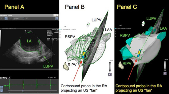
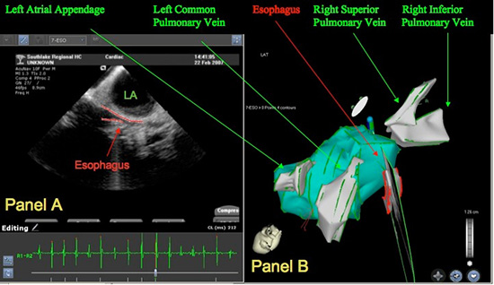
Figure 2. Reconstruction of oesophagus: Panel A illustrates an ultrasound snapshot through the mid left atrium. The red contour behind the posterior wall of the left atrium represents a “slice” through the Esophagus. Panel B shows a 3D reconstruction of the left atrium, the pulmonary veins and the Esophagus built on the basis of ultrasound derived contours
Pulmonary Vein Antrum Isolation
Left atrium was then instrumented with a circular mapping catheter and an ablation catheter via two independent ICE guided trans-septal punctures and the patient was systemically anticoagulated. Pulmonary vein antrum isolation was performed using a previously described approach.6 The ablation catheter was manipulated within the ultrasound derived 3D shell of the left atrium without either having to create a point-by-point anatomy or having to select and superimpose key anatomical sites as is the case with CartoMerge and Ensite Fusion technologies. In brief, a circular mapping catheter was sequentially positioned in each of the anatomical pulmonary vein antra guided by intracardiac echocardiography and fluoroscopy, since the catheter could not be visualized using the CARTO system. Wherever high frequency pulmonary vein potentials were seen, radiofrequency energy was delivered immediately next to the roaming electrode pair of the circular mapping catheter using either a Navistar Thermacool (Biosense Webster) set to the power of 30 – 40 Watt and flow of 30 cc/min or a Navistar DS 8mm tip catheter with power titrated from 40 – 50 Watt and temperature capped at 50ºC. In both instances, energy was delivered to the endpoint of disappearance of pulmonary vein potentials as seen by the circular mapping catheter. In the case of the 8mm tip catheter, energy was titrated down in 5 Watt decrements whenever microbubbles were seen on ICE. Ablation lesion tags were collected towards the 3D map of the left atrium for later correlation with the ICE generated anatomy.
Ablation catheter position was verified using fluoroscopy and 2D real-time intracardiac echo imaging. Catheter position verified using standard means correlated with that seen on the 3D ultrasound-derived left atrial reconstruction throughout the ablation procedure.
In each vein, the circular mapping catheter was initially positioned at the anatomical pulmonary vein ostium, starting at the ridge with the left atrial appendage in the case of the left pulmonary veins and the septal border in the case of the right pulmonary veins. Once no pulmonary vein potentials were seen by the circular mapping catheter at any given position, it was moved towards the roof or the floor of the vein ostium, and ultimately towards the posterior wall of the left atrium, thus covering the entire pulmonary vein antrum.
At the end of the procedure, the veins were remapped using the circular mapping catheter to ensure disappearance of potentials in all PV antra. In patients who were still in atrial fibrillation at the end of the procedure, limited mapping of the complex fractionated atrial electrogram (CFAE) regions took place. The version of software used did not have an automated CFAE mapping algorithm and so identification and ablation of CFAE was at the operator discretion. Those who were still in atrial fibrillation after CFAE ablation were cardioverted and the PV antra were re-mapped in sinus rhythm.
Once the procedure in the left atrium was complete, patients with history of atrial flutter had a cavo-tricuspid isthmus ablation to the endpoint of bidirectional block. Superior vena cava was isolated as well whenever high output stimulation did not suggest that SVC isolation would incur the risk of phrenic nerve palsy.
Fifteen patients, all men, 10 with paroxysmal AF were offered ablation guided using CARTOSOUND technology between February and May of 2007. Average age of the patients was 57 +/- 7 years. Five patients had previously failed Class IC drugs, seven had failed sotalol, nine were refractory to amiodarone and two to dofetilide. Four patients had mild to moderate left ventricular dysfunction. Left atrial size was 44+/-5 mm on average.
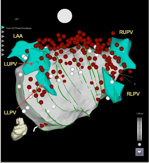
3D maps took 51+/-25 min to create, prior to entering the left atrium and without fluoroscopy. Complete maps of the left atrium, the pulmonary vein and the esophagus were built from 46+/-19 contours. Figure 3 illustrates the relative position of the ablation tags with respect to the map in one of the patients. It became apparent that catheter pressure may cause a substantial distortion in left atrial anatomy. While catheter position on the mid to low posterior wall, the ridge between the left atrial appedage and the left pulmonary veins, the septum and the pulmonary vein ostia was within the 3D ultrasound-derived contour, the catheter reproducibly appeared beyond the atrial silhouette on the high posterior wall, roof and high anterior wall, suggesting that these areas were more prone to catheter deformation.
Figure 3. Deformation of the Left Atrial Wall by the Ablation Catheter. Green lines represent individual ultrasound contours used to reconstruct anatomy of the left atrium and the pulmonary veins. White dots are points added to the left atrial anatomy, red points represent ablation lesion tags. Along the roof of the left atrium, the points acquired by the mapping catheter are outside of the ultrasound derived 3D silhouette of the LA likely secondary to deformation of the left atrium by the relatively stiff catheter. LUPV – left upper pulmonary vein, LLPV – left lower pulmonary vein, RUPV – right upper pulmonary vein, RIPV – right inferior pulmonary vein, LAA – left Atrial appendage
It took on average 234+/-78 min to perform each procedure. Total fluoroscopy time averaged 65+/-12 minutes. Radiofrequency energy was delivered for 89+/-46 minutes. Ten of the patients had adjuvant CFAE ablation and two had ablation for atrial flutter following AF ablation. Seven had SVC isolation. Atrial fibrillation could be terminated with radiofrequency energy delivery in all five patients who presented for ablation in AF. There were no intra or post-procedural complications. At 10+/-1 months of follow-up 11 patients (73%) remain free of recurrent AF following the initial three months blanking period.
Integration of intracardiac echocardiography and 3D electroanatomic mapping was used to guide ablation of atrial fibrillation refractory to medical therapy in fifteen patients with both paroxysmal and chronic substrates. This approach allowed rapid acquisition of real time cross sectional images of the left atrium without having to enter this chamber. The images were then integrated into a registered three-dimensional model of the left atrium without the need for pre-procedural imaging. CartoMerge was not used during this experience. Ablation guided using this technique was successful in eliminating atrial fibrillation in 73% of the patients. Ablation points distorted the left atrial anatomy generated using ICE, demonstrating that the wall of the left atrium can easily deform under the pressure applied by the relatively stiff standard ablation catheter. This needs to be accounted for during point-by-point mapping of the left atrium.
In a recently published experience precision of navigation using the CARTOSOUND system was evaluated.7 In 12 dogs, clips were percutaneously implanted in each cardiac chamber. Three-dimensional maps of the cardiac chambers were then constructed using this system from a family of two-dimensional echocardiographic images. Clip sites were identified on 3D images derived from ultrasound and CartoMerge CT reconstruction images. Precision of navigation to the clip sites was then evaluated using identification of the clip sites using real-time 2D intracardiac echocardiography as the gold standard. The authors found a substantially smaller point-source error when navigating using an ultrasound-derived geometry compared to CartoMerge for both atria and ventricles.
The tip of the ICE catheter as well as the projected ultrasound fan was monitored in 3D CARTO space during ablation. This allowed scanning through the tip of the ablation catheter to monitor and verify tip position using feedback from the navigation sensor. Important anatomical structures such as the esophagus were readily identified.
Point-by-point mapping alone has been the standard for AF ablation in some electrophysiology laboratories. Unfortunately, this procedure is time consuming and may be imprecise. While integration of pre-acquired images may help solve this shortcoming of the point-by-point technique, pre-acquired images have obvious limitations and may not accurately represent the real time cardiac anatomy. Intracardiac echo on the other hand has been shown effective in guiding a variety of electrophysiology procedures by providing real time information necessary to improve the accuracy of ablation, to monitor and prevent complications.
This is a small study providing a very preliminary assessment of this new technology. Some operators proficient in AF ablation but unfamiliar with ICE may have a rather steep learning curve with this approach. Automation of ICE image acquisition in the future may help address this issue. While we generally do not practice electroanatomically guided circumferential pulmonary vein ablation, operators using this approach with or without ensuring pulmonary vein isolation would derive a greater benefit from the CartoSound system than we could demonstrate. Ablation approach used during this experience did not rely on 3D reconstruction of the LA anatomy and is typically guided by 2D intracardiac echocardiography and a circular mapping catheter. An ideal AF ablation toolkit would include real time anatomical mapping using intracardiac echocardiography, 3D electroanatomical imaging system, which could accurately visualize both the ablation and the circular mapping catheter, and catheters that would not deform the left atrial wall. Further studies assessing utility of real time registered integration of ICE and 3D electroanatomical imaging are necessary to define its place in cardiac electrophysiology.
CARTOSOUND technology relies on 3D reconstruction based on 2D images, a non-linear transformation that may introduce some error into 3D modeling. A similar transformation is applied to CT slices used to reconstruct CartoMerge images. CartoMerge images were not used to verify 3D ultrasound-derived anatomy in this study.
We found a significant distortion of the left atrial anatomy involving primarily the roof of the LA with ablation points tagged beyond the ultrasound derived 3D silhouette of the LA. Another group applied this technology to a group of 15 patients undergoing ablation for atrial fibrillation producing somewhat smaller reconstructed left atrial volumes using this technology compared to conventional point-by-point 3D electroanatomic mapping.7 The authors hypothesized that the difference in size of the geometries stems from the distortion of the left atrial anatomy by a conventional mapping catheter, a finding that matches ours.
Unfortunately, while the circular mapping catheter could be monitored by ICE and fluoroscopy, it could not be tracked by the CARTO system, making it difficult to cut down on the high fluoroscopy exposure typical of the PV antrum isolation procedures.
A mapping system combining ICE and 3D electroanatomical mapping can feasibly reconstruct a 3D shell of the left atrium and the esophagus. Ablation guided using this approach appears safe and effective in a small group of patients with a variety of AF substrates. A broader investigation of this novel approach to AF ablation may be warranted.
This is an investigator initiated project, not funded by the industry
Yaariv Khaykin: speaker’s honoraria (Biosense Webster, St Jude Medical, Medtronic)
Allan Skanes: speaker’s honoraria and Physician Advisory Board (Biosense Webster)
Atul Verma: speaker’s honoraria (Biosense Webster, St Jude Medical, Medtronic)
Lorne Gula, Bonnie Whaley, Carol Hill, Marianne Beardsall, Catherine Seabrook, Zaev Wulffhart, Richard Oosthuizen: none