Routine Implant of Biventricular Devices Guided by an Electroanatomic Mapping System - Ready for Prime-Time?
Kim H. Chan, MBBS, PhD, Peter A. Santucci, MD
Department of Cardiac Electrophysiology, Loyola University Medical Center, Maywood, IL, USA.
Biventricular devices play an important adjunctive role in the treatment of heart failure. However, biventricular device implantation is associated with significant radiation exposure and a high proportion of non-response to cardiac resynchronization therapy (CRT). The use of electroanatomic mapping (EAM) during biventricular device implantation may help overcome these issues. This article will review the literature on the role of EAM in biventricular device implantation.
Key Words : Sleep Apnea, Atrial Fibrillation, CPAP, Outcomes, Arrhythmia Control.
Correspondence to: Dr. Peter A. SantucciDepartment of Cardiac ElectrophysiologyLoyola University Medical Center2160 S First AvenueMaywood, IL 60153USA.
Cardiac resynchronization therapy (CRT) with an implantable cardioverter-defibrillator (ICD) plays an important role in reducing heart failure morbidity and improving survival in patients with severe left ventricular (LV) dysfunction, intraventricular conduction delay, and heart failure symptoms despite optimal medical therapy. However, there are still significant limitations to this therapy. For one, biventricular device implantation may be associated with significant radiation and contrast exposure. In addition, approximately 30% of patients do not experience improvements in heart failure symptoms or LV function with CRT.1 Optimizing the degree of response to CRT is complex as multiple factors influence the result, and not all are completely understood.
Electroanatomic mapping (EAM) is a method most commonly employed in the electrophysiology laboratory for the assessment and ablation of tachyarrhythmias. However, in recent years, there has been increasing use of this technology for the implantation of cardiac resynchronization devices. One use of this technology has focused on defining relevant anatomy to aid in the implant, in order to potentially reduce the delivery of radiation and contrast. Another usage is to potentially improve the selection of left ventricular pacing targets. One possible explanation for the nonuniform response rates is suboptimal lead placement with current anatomically based methods. Mapping has demonstrated the heterogeneous ventricular activation patterns amongst patients,2,3 and EAM has been explored as a means of defining the site of optimal LV lead positioning. This article reviews the uses of EAM in biventricular device implantation.
Uses of Electroanatomic Mapping and Potential Benefits
The clinical utility of the 3-dimensional EAM system was first reported nearly two decades ago.4 The advantages of the use of EAM over conventional mapping during electrophysiology studies and complex arrhythmia ablation procedures include its non-fluoroscopic capability and high spatial resolution, thereby leading to reduced procedural time and radiation exposure, as well as improved outcomes. Based on these advantages, it is therefore intuitive that EAM may also aid in device implantation, and more particularly in cardiac resynchronization therapy.
Use of Electroanatomic Mapping in Reducing Radiation Exposure
Reduction in radiation exposure during device implantation is beneficial not only to the patient, but also to the operator and support staff. Despite the widespread use of EAM systems as an adjunctive tool in electrophysiology procedures, its use during device implantation has remained more limited. Pacemaker implantation and atrioventricular node ablation without fluoroscopy was first reported by Ruiz-Granell et al. using the EAM (EnSite NavX) system.5 This was subsequently followed by a case series involving 15 consecutive patients who underwent single chamber pacemaker implantation using the EAM system.6 These patients were compared to retrospective data from 15 patients who underwent pacemaker implantation by conventional (fluoroscopic) means, acting as a control group The total implant time was 59.3±15.6 mins in the EAM group compared to 51.5±12.3 mins in the control group (p = 0.14). All patients except one in the EAM group had no fluoroscopic exposure during their device implantation. One patient in the EAM group experienced a lead dislodgement that required re-operation the following day. In this study, only passive leads were used in the EAM group.
However, radiation exposure in single and dual chamber device implantation remains acceptably low, especially in experienced hands. Of particular relevance is the use of EAM in biventricular device implantation, whereby radiation exposure can be substantially higher compared to single and dual chamber device implantations. The use of EAM in biventricular device implantation was first reported by Del Greco et al., who described a series of 4 patients who underwent CRT-defibrillator implantation using the EnSite NavX EAM system and minimal fluoroscopy.7 In this series, there appeared to be a learning curve in using EAM in biventricular device implantation, with procedural times decreasing in a step-wise fashion from 168 to 124 mins, and fluoroscopy times decreasing from 16.8 to 4.2 mins. Fluoroscopy was also used to perform a coronary sinus venogram. These patients were not compared to those who underwent biventricular device implantation using conventional (fluoroscopic) means.
More recently, EAM-guided biventricular device implantation was reported in a series of 10 patients, which were compared to a retrospective series of 10 (control) patients who underwent biventricular device implantation using conventional (fluoroscopic) means.8 In this study, implantation using EAM was aided by use of the printed venous phase of prior coronary angiograms to help identify target veins, and the use of a decapolar electrophysiology catheter via the right internal jugular vein to obtain anatomy. The authors found that, compared with control patients, those who underwent EAM-guided biventricular device implantation had markedly reduced fluoroscopic times (13.6 vs. 1.5 mins, p < 0.001), reduced use of contrast (54.9 vs. 0.3 cc, p < 0.001), and similar procedural times (178 vs. 162 mins, p = 0.53). One patient with endstage renal disease also avoided use of contrast with the EAM-guided biventricular device implantation. Improvements in functional class and cardiac function post biventricular device implantation were similar between the 2 groups of patients. The above mentioned studies are summarized in Table 1.
Table 1. Summary of studies on device implantation using electroanatomic mapping to reduce radiation exposure
| Study |
Device type |
Details |
Results |
| Ruiz-Granell et al.6 |
Single chamber pacemaker |
15 consecutive patients vs. retrospective series of 15 control patients. Only passive leads were used. |
Total implant time was 59.3±15.6 mins in the EAM group vs. 51.5±12.3 mins for control group (p = 0.14). In EAM group, 14/15 patients had no fluoroscopic exposure, 1 had lead dislodgement. |
| Del Greco et al.7 |
CRT-defibrillator |
Cases series involving 4 patients. No control group. |
Learning curve evident, with procedural times decreasing from 168 to 124 mins, and fluoroscopy times decreasing from 16.8 to 4.2 mins. Fluoroscopy also used for coronary sinus venogram. |
| Mina et al.8 |
CRT |
10 consecutive patients vs. retrospective series of 10 control patients. EAM group used printed venous phase of prior coronary angiograms to help identify target veins, and decapolar catheter via the right internal jugular vein to obtain anatomy. |
EAM group had markedly reduced fluoroscopic times (13.6 vs. 1.5 mins, p < 0.001), reduced use of contrast (54.9 vs. 0.3 cc, p < 0.001), but similar procedural times (178 vs. 162 mins, p = 0.53). |
CRT = cardiac resynchronization therapy; EAM = electroanatomic mapping.
Use of Electroanatomic Mapping in Determining Optimal LV Pacing Site
Despite careful selection of patients, a substantial proportion of patients fail to respond to CRT. The traditional strategy is placement of the LV lead along the posterolateral LV wall, which is presumed to be the site of latest activation in patients with left bundle branch block (LBBB). Indeed, several studies have reported that leads placed at sites of prolonged LV lead electrical delay during native rhythm (i.e. the interval between QRS onset on the surface electrocardiogram to the peak of sensed electrogram on LV lead, corrected for QRS width, corresponding to sites of latest activation) were associated with improved hemodynamic response, LV reverse remodelling and clinical outcomes (heart failure hospitalisation and/or mortality).9-12 However, significant variability in intrinsic LV activation patterns due to heterogeneity in the location of conduction block have been observed in patients with LBBB,2,3 and this may account for the lack of response to CRT in some patients.
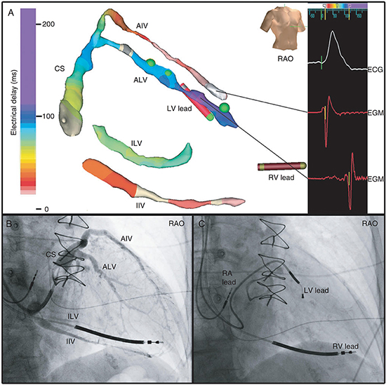
Therefore, a relevant issue is whether the use of EAM can help identify the site of latest activation and optimal site for LV pacing and lead position. The feasibility of such an approach has been explored by a number of studies.7,8,13,14 Consistent with the earlier reports, the study by Niazi et al. involving 32 patients found that sites of latest LV activation were variable, and that the LV lead which was positioned conventionally by a physician blinded to the mapping data was concordant with the latest activated segment in only a small proportion of patients.13 In a more recent study involving 25 patients, Rad et al., using EAM of the coronary sinus venous system (Figure 1), also found considerable variability in site of latest LV activation, being located anterolaterally in 18 patients and inferolaterally in 6 patients (1 patient had limited coronary venous anatomy which precluded assessment).14 In this study, a quarter of the patients had phrenic nerve stimulation at the optimal site, which might have been overcome in the current day by the use of multipolar LV leads (which were not available at time of study) or perhaps LV endocardial pacing. In another recent study, Ginks et al., utilizing noncontact EAM, reported that in patients with myocardial scar or absence of functional block, endocardial or multisite pacing appeared to be required to achieve CRT response.15
Figure 1. (A) EAM of the coronary venous system, with the site of latest activation in purple, with corresponding electrograms (EGMs) shown; (B) corresponding coronary sinus venogram; (C) LV lead placement at site of latest activation. AIV, anterior inter-ventricular vein; ALV, anterolateral vein; CS, coronary sinus; IIV, inferior inter-ventricular vein; ILV, inferolateral vein; RV, right ventricular; RA, right atrial; Red dot, phrenic nerve stimulation (PNS); Green dot, no PNS. Reproduced with permission.14
Apart from site of latest LV activation, LV lead placement at the site of latest mechanical activation has been shown to improve clinical outcomes in 2 recent randomized trials.16,17 Ryu et al. recently described a novel technique combining both intraoperative assessment of mechanical (using custom software) and electrical activation (using EnSite NavX EAM system) of the coronary sinus for guidance of LV pacing site optimization during CRT implantation.18
Spragg et al. examined detailed LV endocardial EAM in patients with ischemic cardiomyopathy, creating maps of LV dP/dt with biventricular pacing, in addition to activation maps of native rhythm in eleven patients.19 They found that in the majority of patients, pacing at traditionally accepted LV pacing sites (mid-lateral LV) yielded suboptimal results. In most patients, pacing immediately below the mitral valve ring in the anterolateral or lateral wall was the most reproducible spot for optimizing LV function, though significant interpatient variability was seen, and often multiple noncontiguous sites could produce similar optimal results. Interestingly, in 8 of 11 patients, optimal pacing sites were located at regions other that the latest activated sites. A study by Derval et al. also suggested that pacing at the optimal site was superior in terms of LV dP/dt when compared to the coronary sinus, lateral wall or latest activated LV wall.20 The studies exploring the use of EAM for optimal LV pacing site are summarized in Table 2.
Table 2. Summary of studies on use of electroanatomic mapping to obtain optimal LV pacing site
| Study |
Details |
Results |
| Del Greco et al.7 |
Case series involving 4 patients. No control group. |
Site of latest LV activation chosen as optimal site. All patients improved by one NYHA class. See also Table 1 for details. |
| Mina et al.8 |
10 consecutive patients vs. retrospective series of 10 control patients. EAM group used printed venous phase of prior coronary angiograms to help identify target veins, and decapolar catheter via the right internal jugular vein to obtain anatomy. |
In some patients, EAM was used to identify site of latest LV activation and optimal LV pacing site (no further details were available from the manuscript). In both groups, patients improved on average by one NYHA class and ejection fraction improved by 13-14%. See also Table 1 for details. |
| Niazi et al.13 |
32 patients enrolled (17 with LBBB – Group A, 15 with RV-pacing induced LBBB – Group B). |
Complex and variable LV activation patterns. The lateral or posterolateral branches were the sites of latest activation in 47 % of group A and 73 % of group B. Sites of LV lead positioned conventionally were concordant with the site of latest LV activation only in small number of patients (18% of Group A patients, none of Group B patients). Clinical outcomes not assessed. |
| Rad et al.14 |
25 consecutive patients enrolled. |
Site of latest LV activation variable, being located anterolaterally in 18 patients and inferolaterally in 6 patients (1 patient had limited coronary venous anatomy which precluded assessment). Clinical outcomes not assessed. |
| Ryu et al.18 |
N/A |
Description of novel technique combining both intraoperative assessment of mechanical (using custom software) and electrical activation (using EnSite NavX EAM system) of the coronary sinus for guidance of LV pacing site optimization during CRT implantation |
| Spragg et al.19 |
Examined detailed endocardial LV EAM and maps of LV dP/dT in 11 patients with ischemic cardiomyopathy. |
In the majority of patients, pacing at traditionally accepted LV pacing sites (mid-lateral LV) yielded suboptimal results. Interestingly, in 8/11 patients, optimal pacing sites were located at regions other that the latest activated sites. |
CRT = cardiac resynchronization therapy; EAM = electroanatomic mapping; LBBB = left bundle branch block; LV = left ventricle; NYHA = New York Heart Association; RV = right ventricle
Unanswered Questions and Future Directions
Although EAM-guided biventricular device implantation show potential in reducing radiation exposure and guiding optimal site of LV lead placement, larger, randomized studies are required to see whether such an approach will result in improved clinical outcomes. Most of the current data is derived from small, single center trials with varying methodology. Often, it is unclear how control patients were chosen. The use of EAM technology also adds an additional significant cost per study,8 and therefore a cost-effectiveness analysis is also required before its widespread use can be recommended. Concerns regarding adequacy of lead deployment and risk of lead perforation without use of fluoroscopy may be overcome with 3D mapping leads with lead body sensors, allowing assessment of slack and helix deployment without the use of fluoroscopy. Currently, although widespread routine use of this technology may not yet be appropriate, it appears reasonable to consider its use in certain groups of patients, such as children, fertile women, and in particular, pregnant women requiring device implantation.
Although there may be promise in the use of EAM for selection of optimal pacing targets, for the time being, further investigation is needed. Many variables affect the ability to place an LV pacing lead by the usual transvenous/coronary sinus route. The pacing site chosen is affected not only by identification of an optimal pacing site, but also by coronary venous anatomy, including vein caliber and tortuosity, accessibility of the site with current leads, capture thresholds, and phrenic nerve stimulation. In addition, there is mixed data and no clear consensus on defining the optimal pacing site. Further clarification is also needed on whether endocardial or epicardial approaches produce results superior to traditional techniques. The value of EAM in improving CRT responder rates in patients with non-left bundle branch block conduction delays also remains to be elucidated. The use of EAM will likely be a useful tool in answering these questions. At that time, it will become more clear whether routine use of EAM systems in device implantation can be recommended.
Dr Santucci has received speaker fees from Biotronik, and fellowship support from Medtronic, Boston Scientific, St Jude Medical, Biotronik and Biosense-Webster.