An Update on the Energy Sources and Catheter
Technology for the Ablation of Atrial Fibrillation
Pawan K. Arora MBBS, James C. Hansen MD, Adam D. Price MD, Josef Koblish, Boaz Avitall MD PhD, FHRS
University of Illinois at Chicago, USA.
The ablation of atrial fibrillation (AF) is an area of intense research in cardiac electrophysiology. In this review, we discuss the development of catheter-based interventions for AF ablation. We outline the pathophysiologic and anatomic bases for ablative lesion sets and the evolution of various catheter designs for the delivery of radiofrequency (RF), cryothermal, and other ablative energy sources. The strengths and weaknesses of various specialized RF catheters and alternative energy systems are delineated, with respect to efficacy and patient safety.
Correspondence to: Boaz Avitall, M.D, Ph.D, The University of Illinois at Chicago, Department of Medicine, Section of Cardiology, 840 South Wood Street (M/C 715) Chicago, Illinois 60612.
Atrial fibrillation (AF) is the most common cardiac arrhythmia, with a prevalence that increases with age to 30 per 1000 between 55 and 60, and 80-100 by age 80.1-6 Patients with AF have a five-fold increased risk of stroke when compared with normal individuals.7 Pharmacologic rhythm control has shown limited efficacy, only slightly better than 50%. In addition, the use of antiarrhythmic agents can be pro-arrhythmic and carry significant side effects.8,9,10,11,12 Currently, the MAZE III operation is the most effective rhythm treatment of AF, with a long-term success rate of over 90%.13,14,15,16,17 The success of the Maze procedure demonstrates that in order to cure AF, it is important to reduce the surface area of the atria into partitions that do not allow the formation of reentrant circuits.18
With a variety of intracardiac catheters and energy sources, growing research suggests that a minimally invasive approach can be applied to treat AF successfully. Among these energy sources are radiofrequency, cryoenergy, laser, microwave and ultrasound. At the present time, radiofrequency energy is the most widely used energy source, and various specialized centers have achieved high success rates in treating arrhythmias with catheter ablation techniques using conventional radiofrequency energy. However, catheter ablation procedures remain technically challenging and operator-dependent, and centers that have less experience have lower success and higher complication rates. Therefore, further developments of catheter ablation technology are still required to improve procedural success and longterm outcomes and to reduce complication rates.
The desirable characteristics of an efficient energy source for catheter ablation should include: (a) ability to form uniform linear lesions; (b) adequate depth for transmural ablation, (c) freedom from contact dependence, (d) short procedure time, (e) lower risk of endocardial disruption/perforation and thrombosis formation, and (f) no injury to extracardiac structures. In this review article we focus on the potential role of energy sources and catheter design for catheter-based treatment of AF.
The evidence for PV isolation
It is now well established that in a subset of patients with paroxysmal AF, one or several foci, which initiate premature atrial contractions (PACs) or recurrent runs of atrial tachycardia (AT), result in the initiation of paroxysmal AF. The most intriguing aspect of this arrhythmia is that the foci are often identified to be within the pulmonary veins (PVs). It is hypothesized that bursts of AT, or even PACs, may lead to atrial electrical remodeling, which in turn leads to persistent and, eventually, chronic AF.19 The current clinical experience with the ablation of paroxysmal AF points to a single or multiple triggering foci that initiate rapid runs of atrial tachycardia that may lead to AF. Additional support to the hypothesis that focal activity may be the cause of chronic AF is provided by another publication of the ablation of chronic AF in humans.20 In this report, linear lesions in the left atrium (LA) were directed at the regions of maximally fractionated electrical activity, resulting in termination of the AF and unmasking of focal AT originating from PV ostia, trabeculated portions of the atrium, and the LA appendage. However, it is also possible that the AT is an iatrogenic result of noncontiguous and/or non-transmural linear lesions.
The unique structural anatomy of the PV insertion into the LA strongly supports the argument that the LA tissues spiraling deep into the PVs, especially the superior PVs, may provide the substrate for atrial reentry arrhythmia.21,22 Muscle fibers form spirals around the PVs, and pacemaker-type cells can be found within these structures, supporting the hypothesis of both ectopic activity and one or multiple reentrant circuits leading to the formation of AT. If this AT is persistent, it will cause atrial electrical remodeling and the initiation of AF.23
Catheters used for Pulmonary Vein Isolation
The introduction of RF current for catheter ablation of cardiac arrhythmias represented a significant stride and an important tool for catheter ablation procedures compared to DC energy and chemical energy. Over years of clinical and research applications, the RF technique has emerged as the most successful and effective energy source for catheter arrhythmias. The radiofrequency band of 30 KHz to 30,000KHz is used for ablating cardiac tissue, with most RF ablation generators operating at 550KHz.24 RF energy is applied as a sinusoidal current through a small endocardial electrode to provide effective tissue heating. The primary mechanism of tissue injury by radiofrequency ablation is thermal. The mode of heating by RF is resistive heating, meaning that only a thin rim of tissue in immediate contact with RF electrode is directly heated. Deeper tissues are not heated as a direct result of dissipation of electrical energy, because tissue heating decreases as a function of 1/r4. Therefore, the deep tissues are heated via conductive heating from the tissue near the electrode-tissue interface.25,26
Presently, the predominant RF ablation catheters in use employ single or bidirectional deflection with several deflection lengths. However, it is common that ablation procedures are significantly prolonged, at times failing as the result of an inability to deliver effective RF energy to the appropriate arrhythmogenic tissues. Although magnetically guided technology may resolve the ability of the catheter tip to reach the targeted tissues, it is markedly more expensive than designing simple catheters that properly fit the intended anatomy.
Myocardial tissue is irreversibly damaged at temperatures over 50°C. Deeper lesions are produced as the catheter tip–tissue interface temperature increases, until it reaches 100°C, at which point plasma boils, resulting in coagulum formation at the catheter tip. This can result in clot embolization, a sudden increase in impedance, loss of thermal conductivity, and/or ineffective tissue heating. In certain situations, excessive heating of the deep tissue layers can result in the production of steam within the tissue, ultimately leading to a “steam pop,” tissue disruption, and possible cardiac perforation. To prevent such events and to monitor lesion efficacy, RF ablation is generally performed in the temperature-control mode.
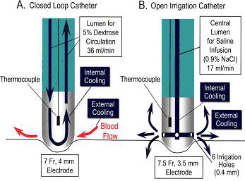
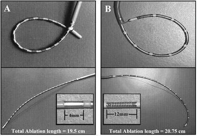
One critical element involved in maintaining effective levels of RF power is to provide electrode cooling, especially in areas of lower blood flow. Two strategies have been devised to accomplish this process. The first approach is to increase the electrode surface area exposed to the blood; thus, the development of 8-to-10-mm tip catheters. This greater surface area increases convective cooling. The second approach is to cool the electrode tip with infusion of saline. Saline infusion allows greater power delivery to the tissue and shifts the point of maximal heating to the tissue itself. Ultimately, this results in deeper conductive heating and the production of deeper lesions.27,28 In general, there are two types of irrigated catheters figure 1. The first type is the closed-loop irrigation catheter, which has an internal thermocouple and continuously circulates saline within the electrode tip. The second type is the open irrigation catheter, which has an internal thermocouple and multiple irrigation holes located around the electrode through which saline is continuously flushed, providing both internal and external cooling. In a direct comparison between open-irrigated and closed-irrigated RF ablation catheters, Yokoyama et al. found that open irrigated systems resulted in greater interface cooling, with lower interface temperatures and lower incidences of both thrombus formation and steam pops than seen with closed-loop irrigated catheters.29
Figure 1. Schematic representation of the irrigated electrode catheters. A, Closed loop irrigation catheter has 7F, 4-mm tip electrode with an internal thermocouple. A 5% dextrose solution at room temperature was circulated continuously through the tip electrode at a flow rate of 36 mL/min, cooling the ablation electrode internally. B, Open irrigation catheter has 7.5F, 3.5-mm tip electrode with an internal thermocouple and 6 irrigation holes (0.4-mm diameter) located around the electrode, 1.0 mm from the tip. Heparinized (1 U/min) normal saline at room temperature was irrigated through the electrode and 6 irrigation holes at a flow rate of 17 mL/min during each RF application, providing internal and external electrode cooling.29
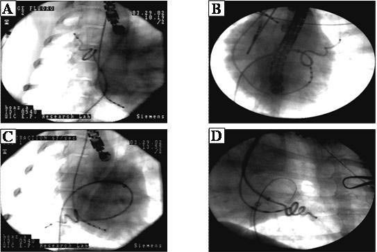
An additional approach to define the ostial region of the PV as well as maintain tissue contact with the ablation catheter tip can be achieved with a simple modification of the current deflectable ablation catheters. The creation of a tight deflection of the distal shaft of the ablation catheter permits insertion of the shaft into a PV with the ablation tip protruding from the vein and deflected 90 degrees to create contact with the LA tissue. The shaft characteristics allow transmission of catheter-handle rotation to the ablation tip via long 11F pre-shaped sheaths designed to engage the PVs. By rotating the catheter handle, torque is transmitted to the ablating tip, which rotates around the orifice. The ablation tip is 8 mm, followed by a 2 mm ring electrode and an additional pair placed 5 mm from the distal electrodes for recording the electrical activity within the PV ostium. Using a long sheath, the catheter is delivered into the PVs across the atrial septum. The position of the ablation catheter tip is ascertained using contrast injection figure 2.
Figure 2. Plates B,C. The J Catheter in the left upper PV
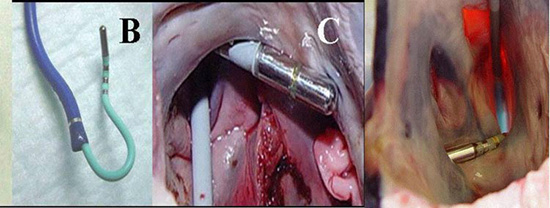
The J catheter was tested in animals were local electrogram amplitude recordings and pacing thresholds were recorded before and after each RF application (55 °C for 1 min) from the distal ablating and ring electrodes. After each circumferential ablation, the intra-PV electrical activity was measured by rotating the catheter within the vein using the proximal recording electrodes on the catheter. PV isolation required 8-11 lesions. Pacing thresholds increased from 3.9±2.1 to 6.1±4.0 mA (84% increase, p<0.0001). P-wave amplitudes decreased from 2.0±1.5 to 1.1±1.2 mV (45% decrease, p<0.001). At the completion of the isolation, no PV potentials were recorded. Post-ablation burst pacing could not induce AF or atrial tachycardia. No PV stenosis was found with any of the lesions likely related to application of the RF lesion in the left atrial tissues.30
This simple modification of the current ablation catheters can easily create circumferential lesions around the PVs and is effective and easy to use. It defines its anatomical position around the PVs and has the potential to reduce both ablation time and radiation exposure without decreasing efficacy of AF ablation and without increasing the current catheter cost.
An additional example of a catheter that is designed to specifically isolate the PV ostia corkscrew shape is shown in Figure 3. This catheter is equipped with 4 12 mm coil electrodes, with two thermistors placed at the edges of each coil to regulate the RF power, adjusting to the maximal sensed temperature from each thermistor.31
Figure 3. PV ostia spiral catheter31
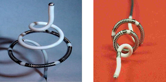
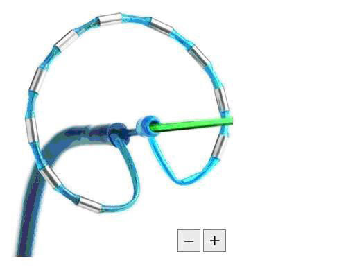
The ablation catheter is introduced into the PVs via a 9 F sheath. Once the tip of the catheter is in the PV, the sheath is withdrawn while maintaining the catheter position in the PV. As shown below, the spiral catheter expands within the vein and the coil electrodes are embedded within and under the orifice of the PV figure 4.
Figure 4. Spiral catheter in Pulmonary veins
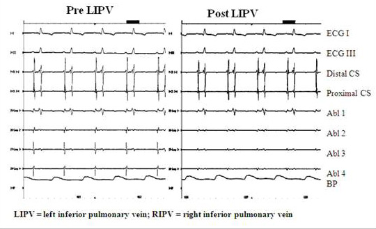
The spiral catheter was tested in animals to assess the safety and efficacy of placing circumferential lesions around the PVs. Lesion efficacy was assessed with pre- and post-ablation changes in pacing threshold, intra-PV electrogram amplitude measurements, PV angiography and intra-PV ultrasound. All of these measurements were taken pre/post ablation and during the final study following 2.5 months of recovery. RF energy was delivered in the temperature control mode and power was delivered to one electrode at the time. Pre-ablation pacing threshold and P-wave amplitude were measured on each electrode Figure 5. Intracardiac Echocardiography (ICE) was used to measure PV diameter before and immediately after ablation. Pulmonary angiography was performed in two perpendicular projections (LAO and RAO) before and after ablation, and during the final study. Transthoracic echocardiography (ECHO) and pulsed Doppler evaluation of left atrial (LA) size and mitral flow was performed before and one month after ablation. Detailed histological evaluation was then performed using H&E and trichrome staining . The average temperature reached was 72 ± 3.6°C. The average power to reach the desired temperature was 23.6 ± 5 Watts applied for 118 ± 8 sec. No perforations, pericardial or plural effusion, or hemorrhage occurred with the use of this technique. LA size, transmitral flow, and PV Doppler flow patterns did not change one month post-ablation. In 11/13 PVs the amplitude of the local electrograms was reduced by 40% (p<0.01), and the pacing threshold increased from 6.9 ± 3.1 mA to more than 10 mA (p<0.04). No visible PV narrowing was seen during final PV angiography. PV circumferential lesions were documented in PVs and no PV stenosis was documented post mortem. However, to create a circular PV isolation lesion the catheter has to be rotated to a different position to create a circumferential lesion.
Figure 5. Pre (left panel) and Post (right panel) ablation electrograms in LIPV. Post ablation the PV potentials have decreased significantly
The Lasso Ablation Catheter
The PVAC (Ablation Frontiers, Inc., Carlsbad, CA, USA) is a 9F, over-the-wire, circumlinear (diameter 25mm), decapolar mapping and ablation catheter figure 6. The 3 mm long platinum electrodes have an outer diameter of approximately 1.5 mm and are spaced 3 mm apart. Each electrode contains a thermocouple positioned on the surface contact side of the electrode. The catheter has 2 control handles. One allows bidirectional deflection of the shaft and the other is used to move the distal tip forward along the 0.032 mm guidewire, allowing a change of the catheter from its circular shape to a spiral configuration and finally a longitudinal shape. The catheter is advanced through the sheath in its longitudinal shape and then deployed in the atria with a guidewire positioned in the vein.32
Figure 6. PVAC (Decapolar Mapping and Ablation Catheter)33
The GENius RF generator (Ablation Frontiers,Inc., Carlsbad, CA,USA) is a multichannel, duty cycled RF generator capable of independently delivering energy simultaneously to a maximum of 12 electrodes. RF energy can be delivered in unipolar (between ablation electrode and reference patch) and bipolar (between 2 adjacent ablation electrodes) configurations. Pairs of electrodes can be selected independently. During RF application, energy delivery is controlled by a software algorithm that modulates power to reach the user-defined target temperature (60˚C), but always limits power to a maximum of 10W per electrode. In this way the ablation is “temperature controlled”. Although with this 10W power limit the peak power delivered to each electrode is lower than with a non-irrigated 4 mm tip catheter, the current density applied at the tissue surface is approximately the same due to the smaller surface area of the electrodes. To achieve PV isolation it is necessary to rotate the catheter and apply overlapping circumferential lesions.32
Boersma et al studied 98 patients with paroxysmal or persistent AF to evaluate the feasibility and safety of this multielectrode catheter. All target PVs were isolated using this catheter, and follow-up after 6 months without antiarrhythmic drugs showed freedom from AF in 83% of patients. This study also demonstrated that fluoroscopy and procedural time appear to be shorter than those associated with current AF ablation techniques, without the need for sophisticated mapping and/or steering modalities.33
The loop catheter design for the creation of linear lesions in an effort to ablate AF was introduced in 1997. There are two main loop catheter systems mostly used for experimental studies:24 4-mm ring and 14 12-mm coil electrodes (Boston Scientific, EP Technologies, Sunnyvale, CA, USA).34 Both catheter designs are shown in figure 7. The first catheter system has 24 4mm ring electrodes that can create loops in the atria. Although AF could not be induced after the completion of the lesion set using ring electrodes, sustained atrial tachycardia (AT) could be induced in 25% of the hearts. In an effort to increase the efficiency of the ablation system, the second loop catheter was designed with 14 12-mm long coil electrodes 2 mm apart, equipped with two thermistors that were positioned at the two edges of each coil. The power is regulated to the maximal temperature measured between the two thermistors. Depending on the magnitude of the guidewire retraction and the size of the catheter portion extending from the sheath, the electrode portion of the catheter can form loops of various sizes. The body of the catheter applies pressure on the thin atrial walls and forces them to stretch around the catheter, maintaining consistent electrode–tissue contact along the entire length of the ablation portion of the catheter. Because the forces that are applied to the atrial walls are distributed along the catheter shaft around the loop, it is presumed that no single point is exposed to excessive forces. A locking mechanism holds the catheter and guidewire firmly in position.36
Figure 7. The loop catheter system. (A) 8F with 24 4-mm-long ring electrodes spaced 4 mm apart. (B) 8F with 14 12-mm-long coil electrodes spaced 2-mm apart. A soft, braided pull wire attached to the distal tip of the catheter can be retracted into the long guiding sheath to deflect the catheter tip to create a loop of various sizes.34
The loop catheter was tested in the animal model, linear lesions were placed in five anatomic targets. These sites were chosen based on the Maze procedure, the need to create atrial linear lesions, and the mechanical characteristics of the loop catheters that cause them to adapt to the maximal circumference within a globular chamber. By positioning the sheath at different levels, a variety of positions can be achieved in the RA and LA figure 9,10. Each repositioning of the catheter was counted as an additional linear lesion. The linear lesions were created in a variety of sequences at five targeted locations (figure. 8). The electrodes can be used to record electrical activity and deliver RF power for ablation.34
Figure 8. Loop catheter positions. RA Loop (upper left panel) circular lesion from the anterior septal tricuspid valve (TV) to the right atrial appendage, to the superior vena cava (SVC) and back to the inferior vena cava (IVC): RAV (upper right panel) vertical loop connecting the SVC, IVC, and RA lateral wall; LAH (left lower panel) circular horizontal lesion placed under the pulmonary veins (PVs) in the mid-LA, above the mitral valve (MV), as indicated by a coronary sinus catheter and the atrial and ventricular electrograms recorded from each of the 24 electrodes on the catheter; LAV (middle lower panel) a vertical lesions extending from the MV annulus medial of the PVs; LAV (right lower panel) a vertical lesion extending from the MV to the LA appendage, lateral of the PVs.34
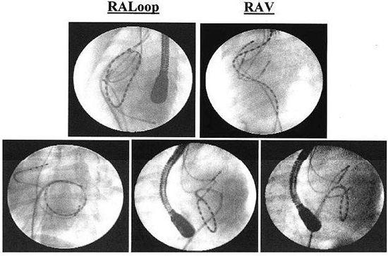
Figure 9. The Loop catheter is deployed in the left atrium of a human heart during an endocardial, catheter-based Maze procedure. The view is left anterior oblique. The catheter emerges from the transeptal sheath and a loop is created after the tip of the catheter is pulled to the end of the sheath with a pull-wire as the body of the catheter is advanced into the atrium. There are 14 individual ablation coils on the catheter. Coils number 1, 4, 7, 8, 11, and 14 are more radiopaque to improve identification. An intracardiac echo probe can be seen in the body of the right atrium35
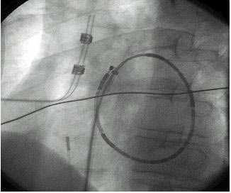
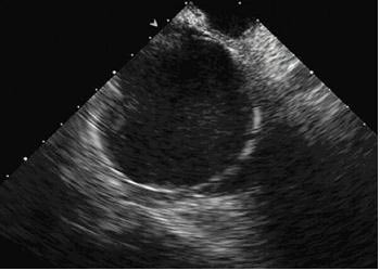
Figure 10. A view of the multiple-electrode loop ablation catheter deployed in the left atrium as seen from a phasedarray intracardiac echo probe located in the right atrium. A subset of the individual electrode coils can be identified. Intracardiac echo can be useful during left atrial catheter ablation procedures to optimize tissue contact35
Lesion Formation with the Loop Catheter
The most important determinant in the effective creation of a RF lesion is the electrode–tissue contact. Using the variable loop concept, the globular shaped atrial chambers will adapt around the catheter providing continuous contact. When using temperature control with this technology, over 90% of the lesions created in both atria were both contiguous and transmural; the incidence of impedance rises was minimized. The catheter can be used to create linear lesions 6 mm wide and up to 16 cm long with minimal manipulation. Linear lesions were made by ablating at individual electrodes. The time required to create an entire linear lesion could be greatly reduced by using a closed-loop system to simultaneously deliver RF power to multiple electrodes to maintain a set temperature. Having multiple ablation electrodes on a single shaft allows for minimal catheter manipulation in creating long linear lesions and, therefore, reduces both thromboembolic risk and radiation exposure. Once the catheter is in place, it remains in position for the duration of the power application to all of the electrodes. Initial efforts to assess the efficacy of this technology for the ablation of AF in humans has not resulted in a great success most likely related to the lack of PV isolation.
The Development of Balloon and Balloon-like Catheters for the Isolation of the PV
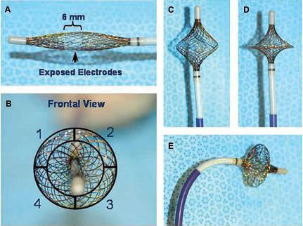
Despite the promising results from the use of different energy sources for circumferential ablation of PVs, their limited clinical efficacy may arise from variable PV ostial sizes, orientations, and bifurcations. To simplify the PV-antrum isolation procedure, it would be desirable to use a single device capable of both high-resolution recording and RF current delivery. Recently, an expandable, variably shaped catheter (MESH, Bard Electrophysiology) has been developed that may overcome these limitations. The HD Mesh Ablation System (Bard Electrophysiology, Lowell MA, USA) comprises a 36-pole, high-density mapping and ablation catheter which has a braided, expandable mesh electrode configuration mounted onto a non-steerable 8F shaft. The mesh electrode is constructed of 36 wires that can be used to record 36 bipolar electrograms (EGM) Figure 11. The geometry of the electrodes is two opposing 18-electrode interwoven helices with thermocouples placed at the edge of each of four quadrants of the circumference to provide temperature sensing during ablation. Figure 12 shows a schematic representation of the HD Mesh Ablator catheter construction, showing the relative position of the four temperature sensors (TC). The HD Mesh Ablator catheter delivers pulsed RF energy via Pulsed RF Controller, a device that accepts the output of a compatible RF generator and distributes the RF energy to the electrodes of the BARD HD Mesh Ablator in a pulsed-energy manner. Pulsed RF is delivered to the HD Mesh catheter electrodes to create the desired lesion geometry. The RF Controller uses temperature information sensed by the thermocouples on the HD Mesh Ablator to titrate the pulsed RF energy delivery to the catheter.37,38
Figure 11. HD Mesh Ablator Catheter schematic showing interwoven double helix construction38
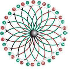
Figure 12. The MESH catheter is a single device capable of highresolution recordings and circumferential or segmental RF current delivery. Panel A— undeployed MESH catheter, note the 6 mm exposed wire band that constitutes the electrodes is shifted distally to the center of the MESH (arrow). This allows forward facing when fully deployed. Panel B—front view illustrating the MESH’s 4 quadrants each capable of selective operation. Panels C, D, and E shows the MESH at partially, fully deployed and deflected, respectively37
Balloon Technologies for PV Isolation
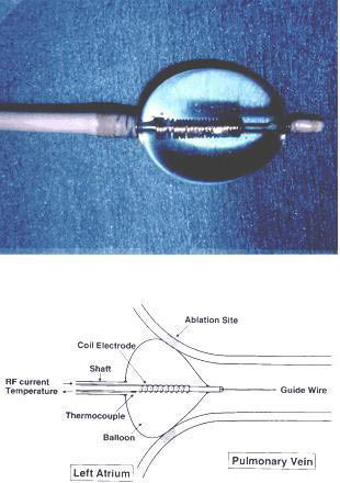
The RF hot balloon technology is another technique for isolating the PV ostia. Tissue heating with the balloon is enhanced by the temporary obstruction of blood flow. The balloon is filled with saline and contrast medium, which allows the balloon size and location to be visualized on fluoroscopy. The saline is heated internally by RF power applied to two ring electrodes located on the catheter shaft within the balloon. This technology, although simple, is perhaps adequate for small vessels, where the size of the heating chamber is only 0.5 to 1 cm in diameter (figure 13). It is likely that the size of the human PV is too large for this technology to create adequate heating at the PV atrial junction.39
Figure 13. The radiofrequency ablation transballoon catheter used in this study. (Top) Photograph of a balloon 1.5 cm in diameter, inflated with fluid and equipped near the distal end of the catheter. A coil electrode with a thermocouple sensor is mounted along the tube inside the balloon. (Bottom) This schematic illustration shows the balloon being wedged at the junction between the pulmonary vein and left atrium. The body of the catheter is 90 cm in length, and a 12F main shaft containing a 4F inner tube, as well as its central lumen, can accept a 0.035-in. guide wire. Shaded areas represent the ablated sites located at the pulmonary vein ostium39
Cryothermal energy produces lesions through hypothermic exposure, with a very different mechanism of tissue injury from RF. Cryotechnology has been used for cardiac ablation for three decades, but catheter-based ablation has been a more recent development. Cryolesions are generated by applications of a cryoprobe cooled with liquid nitrous oxide for 2-5 minutes.40 Progressive cooling of the cardiac tissue slows down conduction and eventually blocks electrical activity when the temperature is reduced to 0 to -20 °C. Permanent lesions are created when temperatures are reduced to -60 to -80 °C.41 Applying the cryoprobe to the tissue surface causes the formation of a hemisphere of frozen tissue, or iceball. The size of the cryolesion is determined by a variety of factors including temperature, the size of probe used, and the duration of freeze cycles to which the tissue is subjected. The potential advantages of cryoablation over RF for ablation include a low risk of endocardial disruption causing cardiac perforation, reduced incidence of thrombus formation, and stable adhesion of the catheter tip to the endocardium during freezing.42
Cryoablation of Cardiac Arrhythmias
The use of low temperature as a therapeutic agent in the treatment of cardiac disease can be traced to a report by Harrison et al.43 in 1977 which described a new method of producing AV block. Since that early report, the use of cryotherapy in the treatment of tachyarrhythmias has expanded as new techniques have evolved.44,45 In 1980, Klein et al.46 cryoablated the AV node to treat a recurrent supraventricular tachycardia followed by implantation of a cardiac pacemaker. In subsequent years, tachyarrhythmias related to accessory pathways and AV nodal reentery were successfully managed by cryoablation. Atrial fibrillation, often treated by Maze procedures, can be managed without surgical excision through cryoablative procedures. Cox47,48 have used surgical incision combined with cryoablation of the coronary sinus to ensure interruption of conduction across the posterior-inferior portion of the left atrium. Gaita and associates49 have successfully treated atrial fibrillation by linear cryoablation of the tissue between the four pulmonary veins and the mitral annulus. Recently, arrhythmias have been treated by two-step cryotherapeutic techniques involving reversible electrophysiological mapping followed by targeted ablation. Skanes, et al.50 have used cryo mapping to demonstrate the functionality of potential ablation sites without provoking permanent injury. The two-step procedure is designed to identify and ablate arrhythmogenic areas within the myocardium. Identification of the focus of aberrant excitation (ectopic foci) is critical to the success of this procedure. Recent clinical studies have demonstrated that transvenous cryoablation is a safe and feasible method for PV isolation for treatment of AF.51,52 Skanes et al. reported the initial results of a novel circular cryoablation catheter with a 64-mm freezing segment for PV isolation (Arctic Circler, CryoCath Technologies). This study has shown a 91% acute success rate for PV isolation and improved arrhythmic control in 78% patients after one or two procedures.53
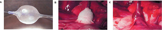
Avitall et al demonstrated that new cryo balloon technology can safely and effectively electrically isolate the PVs in dogs . The cryo balloon catheter (Boston Scientific Corporation, Natick, MA, USA), shown in figure 14, creates cryo lesions by delivering liquid N2O into the semi compliant balloon (15-22 mm diameter).54 After multiple consecutive cryo lesions no PV stenosis was noted 3 months after ablation. After cryo ablation, PV electrograms was eliminated and tissue recovery exhibits no cartilage formation. Acute tissue hemorrhage and hemoptysis are short-term complications of cryo ablation. Further development of catheter designs, such as use of a larger turnip shaped balloon will allow for improved adaptation of the balloon to the human PVs.
Figure 14. Functional illustration of the cryoballoon catheter. A: The cryoballoon with a central lumen guidewire at −70◦C. B: Cryocatheter with formation of an ice ball at the left superior pulmonary veinleft atrial junction. C: After rewarming, hemorrhage is seen within the tissue54
Microwave energy represents a portion of electromagnetic spectrum occupying roughly the frequency range between 500MHz-100MHz. In contrast with radiofrequency, heating with microwave does not result from current flow through the tissue. The mechanism of heating from high-frequency microwave energy is dielectric. Dielectric heating occurs when the propagating electromagnetic radiation interacts with biological tissue, causing the dipoles (particularly water molecules) to oscillate and rotate under the influence of the alternating electromagnetic field. This results in conversion of electromagnetic energy to kinetic energy (or heat).55 Tissues with higher water content, such as cardiac muscle, will allow better energy transfer during propagation of the microwave. This mode of heating, gives microwave ablation the potential for a greater depth of heating, possibly resulting in a larger lesion size. Also, the delivery of heat directly to the deeper tissues reduces surface heating, with less endocardial disruption or coagulation formation. Recent studies have shown that the acute histological lesions of microwave were similar to RF, but the chronic lesions using microwave energy were deeper and wider than with RF.56
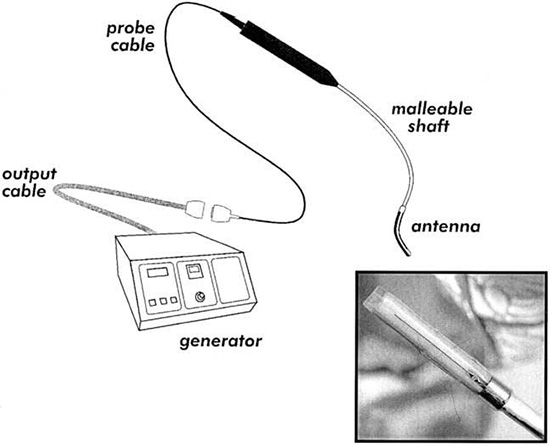
Whayne et al conducted a study to determine the effect of various microwave antenna designs, frequencies, and ablation times on the radial tissue temperature gradients and lesion size. These were compared to RF lesions of similar durations. The major findings of the study were that 915- and 2450-MHz microwave antennas had similar tissue temperature profiles and produced lesion sizes that were not significantly different figure 15. The time course of lesion formation with microwave ablation was significantly longer than that seen with radiofrequency ablation, but the microwave lesion continues to increase in size over a 600 sec of energy delivery while the RF lesion reaches steady state by 60 sec. Another study demonstrated that ablation depth can be predictably controlled by microwave energy power and ablation time, and that the temperature at the tissue surface remains below 100˚C over the time required to produce a 6 mm deep lesion, thus preventing endocardial charring, carbonization, cavitation, and disruption.58 Microwave ablation has been shown to be safe and efficient method and have potential advantages over radiofrequency ablation as shown in following table.
Table 1. Comparison of Cryoablation versus Radiofrequency Ablation
|
Advantages |
Disadvantages |
| Cryoablation |
1. Marked differences inlesion morphology (minimal collagen formation).
2. Preserved atrial contraction and size.
3. Marked reduction in the risk of stroke (no char).
4. Assessment of arrhythmogenic source prior to ablation (cool mapping). |
1. Pressurized gas system.
2. Complexity of control and delivery
3. Potential gas toxicity to the operator and patient.
4. Cooling of the patient.
5. Intramural hemorrhage and risk of hemoptysis.
6. Requires tissue contact |
| Radiofrequency
Ablation |
1. Simple, well-proven technology.
2. Ability to assess contact.
3. Assessment of temperature.
4. Limited tissue damage. |
1. Difficulty of uniform assessment of tissue contact.
2. Significant amount of collagenand cartilage/calcification.
3. Moderate risk of stroke, PV stenosis.
4. Atrial shrinkage.
5. Moderate reduction in atrial mechanical function. |
Figure 15. Microwave ablation system. Close-up of ablating probe [inset]57
Ultrasound Balloon and HIFU Balloon
Another ablation strategy is the use of ultrasound technology to focus the heat dissipation caused by sound waves into atrial tissues. Sound is a propagation of oscillatory displacements of atoms/molecules around their average position in the direction of propagation. When the cyclical events occur at frequencies of >20,000 Hz, the sound is defined as ultrasound. The energy transported by an ultrasound beam is attenuated as it propagates through viscous media such as human soft tissues. The attenuation partly represents a conversion of ultrasound energy into heat.60 Pressure waves (sound waves) propagating in gas-containing tissues cyclically expand (explode) and shrink (implode) microbubbles in the tissue, a process known as cavitation. This represents a major mechanism of damage to tissues exposed to high-intensity ultrasound (2–20 MHz). Ultrasound beams can be treated in a manner analogous to light beams, including focusing (ultrasonic lens) and minimization of convergence and divergence (collimation).61 These manipulations allow for ultrasound to be directed toward confined distant (deep) tissues, a pivotal capability of therapeutic ultrasound.62>
The amount of ultrasound energy transferred to the tissue is proportional to the intensity of the wave and absorption coefficient of the tissue. Due to this property, ultrasound ablation does not require direct contact with the myocardium, as compared to RF ablation. Ultrasound energy falls off proportionally with the distance (1/r) whereas RF ablation current density falls off 1/r4. This feature allows ultrasound energy to create deeper, transmural lesions. The ability of ultrasound to be collimated through a fluid medium makes it ideal for a balloon delivery system. In this method, an ultrasound transducer is mounted on a catheter shaft within an expandable balloon. As a result, a balloon ultrasound ablation catheter system (Atrionix, Inc., Sunnyvale, CA, USA) delivered with an over-thewire technique has been developed for AF ablation.63 The system is advanced over a guidewire into the target pulmonary vein. Ablation system performance and tissue heating were monitored and confirmed by thermocouples on the balloon and the ultrasound transducer. A cylindrical ultrasound transducer is mounted axially near the distal end of the catheter, with a saline-filled compliant balloon that is inflated over the region of the transducer. An occlusive pulmonary venogram is taken to confirm the transducer position.
Table 2. Comparison of Radiofrequency with Microwave59
| Features |
Radiofrequency |
Microwave |
| Clinical experience |
+++ |
+ |
| Potential for endocardial Disruption |
High |
Low/ Medium |
| Thrombogenicity |
High |
Medium |
| Mapping capability |
Limited |
NO |
| Ability to create transmural lesion |
Require optimal Contact |
Optimal contact/ antenna orientation required |
| Lesion size |
++ |
+++ |
| Linear lesion |
++ |
++++ |
| Perforation rate |
|
|
|
Low |
Low |
| Procedure time |
Shorter |
Longer |
| Injury to adjacent
structures: |
|
|
| Phrenic nerve |
+++ |
Unknown |
| Esophagus |
+++ |
++ |
| Coronary artery |
+++ |
+ |
| PV stenosis |
+++ |
no |
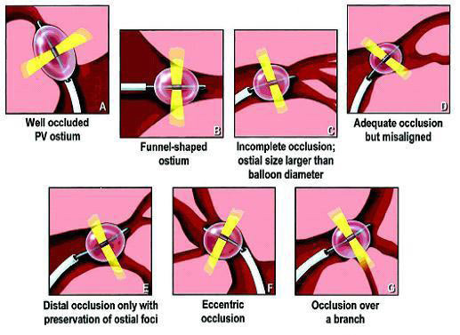
Surprisingly, several applications were required to achieve isolation of the pulmonary veins (PVs). Overall, acute procedural success was achieved in only 73% with ultrasound balloon systems, and long-term cure was observed in about 30% of patients. During PV ablation, only 40% of the ostial lesions reached a temperature of >60°C in patients with recurrence of AF, compared with 64% of those who were free of recurrence. The variability of the PV anatomy was thought to be the main reason for system failure figure 16. In addition, the system delivered a narrow band of ultrasound energy radially from a centrally located transducer. This limitation in lesion po sitioning prevented the operators from including the antrum of the PVs in the lesion boundaries.
Figure 16. Some anatomic variants that potentially are responsible for ineffective delivery of ultrasound lesions: (A) well-occluded pulmonary vein ostium;(B) funnel-shaped ostium; (C) incomplete occlusion, where ostial size is larger than balloon diameter; (D) adequate occlusion but misaligned; (E) distal occlusion only with preservation of ostial foci; (F) eccentric occlusion; (G) occlusion over a branch64
The HIFU (High Intensity Focused Ultrasound) technology was introduce in an effort to overcome some of the limitations presented with the initial design of the ultrasound ablation balloon. HIFU energy travels up to a distance of 10 mm through all layers of the left atrial wall. It is delivered in three sequential phases from endocardium to epicardium. During the first phase the energy ablates the subendocardial tissue. The second phase ablates myocardial tissue, and epicardium is ablated during the final phase.
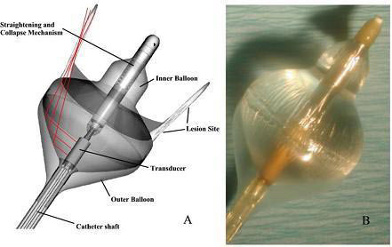
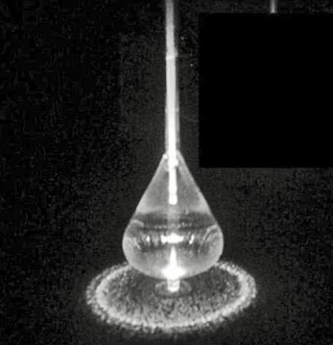
High-intensity focused ultrasound was delivered by the Epicor Cardiac Ablation System (St Jude Medical, St. Paul, MN, USA) figure 17. The system consists of four main components: (1) the Ablation Control System (ACS), which provides fully automated ultrasound energy to the transducers and continuously monitors frequency, temperature and energy levels; (2) the Positioning and Sizing System (PAS), which is placed around the pulmonary veins and measures the appropriate size for the UltraCinch band; (3) the UltraCinch ablation device, which creates a continuous transmural lesion around the orifices of pulmonary veins; and (4) the UltraWand, which provides additional linear ablation lesions.65 Focused ultrasound ablation was performed using an investigational catheter designed to deliver forward directed, focused ultrasound energy (Transurgical Inc., Setauket, NY). The system is composed of a multi-lumen 8 Fr main shaft, with a central lumen for passage of a 0.035-in wire, and separate lumen for access to both an inner and outer balloon. The liquid/gas interface between the two balloons creates an impedance mismatch, allowing reflection and focusing of the ultrasound energy. The focus zone is ring shaped and designed to have its peak intensity 2 mm off the surface of the distal portion of the balloon, schematically represented. The straightening and collapsing mechanism is also located centrally within the inner balloon on the distal catheter shaft figure 18.66
Figure 17. High Intensity Focused Ultrasound (HIFU) Focused ultrasound energy originating from the concave transducer and visualized through a Schlerein effect (fluid-phase laser illumination to visualize the ultrasonic beam). The beam converges at the focal distance and dissipates beyond that point. The focal distance is fixed and determined only by the radius of the curvature of the transducer
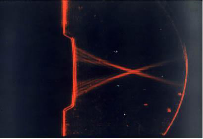
Figure 18. Focused ultrasound ablation catheter. (A) Diagram of the double balloon ablation system, composed of an inner (sterile water/contrast) filled balloon with maximal inflated diameter of 23 mm, as well as the outer carbon dioxide filled balloon. Within the proximal portion of the inner balloon is the ultrasound transducer, emitting radially directed energy. (B) Photograph of the focused ultrasound system following inflation66
A 103-patient trial, conducted at 5 centers in 4 European countries, was the first clinical feasibility study of AF ablation with HIFU applied epicardially on the beating heart. The authors reported that the majority of the surgical procedures were conducted through a median sternotomy; however, 8 of the ablative procedures were performed through a minimally invasive approach. There were no attempts to exclude the left atrial appendage. During the ablation procedure, the Epicor system was placed so that lesions were formed encircling all 4 pulmonary veins. In addition, in 34% of the patients, the handheld Ultra Wand was used to create a single, epicardial mitral ablation line (also created epicardially) extending from the pulmonary vein lesion down to the mitral valve annulus. The duration of the entire ablation procedure averaged about 12 minutes (mean time of actual ablation was 9.7 minutes), all of which was off-pump. During all but 2 minutes of this time, the surgeons were free to prepare for the subsequent heart surgery. Therefore, the researchers concluded that the “AF ablation portion of the procedure added an average of only 2.2 off-pump minutes to the overall combined operative procedure.” They also noted that “no extra time was required for epicardial fat dissection or removal.”
Freedom from AF or atrial flutter at 6-month follow-up was evaluated in 94 patients. There was an 85% success rate in the entire group at 6 months, with 88% success in the patients who received the additional mitral ablation line. In the subset of patients with continuous AF, freedom from AF at 6 months was 80%. Among patients with paroxysmal AF, 100% were AF-free at 6 months. The investigators found that duration and type of AF were 2 factors that independently increased the risk of AF recurrence after surgical intervention (P = .03 and P = .01, respectively). There were no early or late complications or deaths related to either the HIFU device or the ablation procedure, and there were no instances of left atrial reentrant tachycardia or left-sided flutter. A total of 8 pacemakers were implanted during follow-up, including 4 for complete heart block and 4 for sinus node dysfunction. In comparison to these results, the gold-standard surgical Cox Maze procedure has demonstrated 80% to 95% AF cure rates over the long term. However, the study authors point out that HIFU ablation offers several advantages over both traditional surgery and other ablation energy sources, which still require significant additional pump and aortic crossclamp times. The Epicor HIFU ablation procedure can be performed completely off-pump via a minimally invasive approach, and it preserves the endocardial layer, thus avoiding problems associated with gradient-driven ablation technologies. Moreover, there is no need to remove or dissect epicardial fat prior to the ablation, and the system can create a transmural lesion (and a mitral line) throughout the entire range of thicknesses of the atrial wall.67,68
Light amplification by stimulated emission of radiation (laser) produces a monochromatic, phase coherent beam at a specific wavelength. This beam can be directed for a specific duration and intensity and as it penetrates into the tissue, after which it is absorbed and scattered. The photo-thermal effect occurs with the absorption of photon energy, producing a vibrational excited state in surrounding molecules. By absorbing this energy, the tissue is heated and a lesion is created. Laser energy can create deeper lesions with less reliance on thermal diffusion, and can reduce tissue vaporization and coagulum formation. Prior experimental studies have shown a significant linear correlation between the total delivered laser energy and the lesion dimension.69 With the use of low-power energy settings, no crater formation was noted, and lesion depth was more related to duration of application rather than the power of the application. Histologically, laser lesions were homogeneous and sharply demarcated, without epicardial crater or endocardial thrombus formation. This indicates that the focused nature of the energy below the tissue-device interface minimizes the collateral atrial tissue damage that can compromise contractility and become arrhythmogenic substrate figure 19.
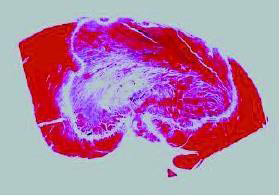
Figure 19. A transmural lesion from laser photocoagulation after 40-second application. The endocardial surface was relatively spared due to cooling from the circulating blood70
The efficacy of the laser balloon depends on good contact around the balloon circumference. In view of this, fiber optic technology is being developed to facilitate the establishment of contact once the balloon is deployed and to improve the performance of such systems. Nd-YAG laser and Diode laser have been used in clinical applications. Previous canine experiments have shown that Nd-YAG laser could create deep, continuous, linear lesions over the myocardium both in vitro and in vivo without any evidence of tissue charring or vaporization.70 Diode laser, a continuous low-energy laser with a wavelength of 980 nm, can minimize endocardial disruption, charring, and clot formation, allowing for more precise lesion creation.71
A laser balloon has been developed to allow the delivery of circular beams of photonic energy to perform PV isolation without PV stenosis and with minimal endothelial disruption. Photonic energy is delivered through a fiberoptic balloon catheter with a 12 Fr collapsed profile Figure 20. The light is transferred from the fiberoptic core using a modified glass fiber tip, through an optically transparent shaft into the balloon, and projected as a ring onto the distal balloon surface. The balloons used were 21 mm or 26 mm in diameter, and the projected ring had a maximum diameter of 17 mm and 22 mm, respectively. The balloon is filled with a 3ml mixture of contrast and D2O (Deuterium Dioxide). D2O is used to eliminate self-heating of the balloon by shifting the absorption to wavelengths longer than the 980 nm utilized. D2O has been used in humans and animals for measuring water spaces, and if inad vertent rupture of the balloon occurred, the small amount of D2O would not be expected to have any deleterious effects. The intensity of the emitted light around the ring delivered to the tissue varies by less than 15% and is continuous with no gaps.72 A linear laser delivery may offer a number of potential advantages over conventional radiofrequency catheter ablation: (1) the laser diffuser is a single flexible and compliant fiber that can create thin lesions; (2) continuous intimate contact between the catheter and the endocardium may not be essential for delivery of laser energy; (3) the laser diffuser is Teflon coated and is not directly heated during energy delivery, and thus is not prone to char formation on the catheter; and (4) laser energy delivery is not subject to disruption by rises in impedance.
Figure 20. The laser balloon ablation catheter. The laser balloon ablation catheter filled with D2Ois shown with a projected circular beam of light to simulate the photonic energy beam71
Catheter Approach to the Creation of Linear Lesions for the Ablation of Atrial Fibrillation
Initial experience has shown that AF ablation in the RA is possible but with very low (13-42%) success rate. Greater success can be achieved with linear lesions in both atria in patients with paroxysmal AF, with reported success rates of over 62%1-4,73-81 No long-term success data is available for chronic AF. Most of the procedures have been done with the use of the catheter drag technique and its considerable complication rates. We have also learned that the current ablation technology is not suitable for the creation of transmural contiguous linear lesions, thus subjecting the patient to the prolonged procedures with considerable complication risk. The use of the loop catheter design and perhaps other designs of ablation technology specifically targeted for the creation of linear lesions should be developed if the catheter approach for the ablation of AF is to succeed.
The goal of catheter-based ablation of AF should be safe, minimal tissue destruction allowing the restoration of NSR. Additionally, it should be combined with preservation of atrial mechanical transport to prevent the development of thromboembolic events and allow for full hemodynamic benefits to the patient. To justify exposing the patient to this procedure, a high safety margin is imperative. Theoretically, ablating the majority of the atrial tissues can terminate AF; however, if mechanical function is not restored, the risk of thromboembolic stroke will remain, requiring continuous anticoagulation. Furthermore, other than rate control, no mechanical benefit will be provided to the patient. If this is the outcome of a catheter-based AF intervention, AV node modification followed by permanent pacer insertion and continued anticoagulation may be a more appropriate therapy for those highly symptomatic patients whose medical therapy has failed. Such an approach presents with minimal acute risk and often is rewarding.82
In this paper we have summarized the effort made to date in the development and testing of catheter-based systems and the development of methodologies for the effective ablation of AF in experimental models. However, the ablation of AF has been associated with mixed results and numerous complications. It is thought that patients with paroxysmal AF require PV isolation and those with persistent AF need more extensive ablation involving linear lesions. The concept of ablating the tissues exhibiting maximal fractionated activity and or those with the maximum dominant frequency has yet to yield consistent results. It remains to be seen if catheter-based AF ablation in the human atria provides long-term protection from AF. More importantly, incomplete lesions may introduce new substrate for reentrant arrhythmia by leaving gaps in ablation lines creating atrial tachycardia. The medical management of such arrhythmia may be significantly more difficult requiring additional ablation procedures. Thus, at this time the guiding light for the effective ablation of AF remains the Cox MAZE template. We believe that with an appropriate catheter ablation strategy targeting the complex LA anatomy, such as balloon ablation devices for PV isolation and expandable loop catheters to create linear connecting lesions, it may be possible to reproduce the MAZE-type atrial lesions.